PROTOCOL INDEX EXAMPLES
PRODUCT REFERENCE GUIDE
149
7. Enter a Header and Terminator for the incoming message from the scale in the
fields provided. Use the
“The Text Entry Tool” on page 81 to create the Header
and Terminator, in this example <STX> and <ETX>.
8. Select a length for the message from the Length Type drop-down list. In this exam-
ple Variable Length is selected.
9.
Enter NoScale for t
he No Index String. This means “NoScale” will be attached to
the outgoing host message if nothing is received from the scale.
10. Select Trailing from the Refe
rence Edge drop-down list. This indicates the back/
trailing edge of the box is the reference point. Trailing is the normal setting for a
message from scale.
11. In the Dis
tance
to Trigger Line, enter the measured distance from the trigger to
the expected scale transmission location on the conveyor belt. This distance will
have been set up in the scale configuration. This parameter specifies the distance
from the Trigger Line (Trigger Source) to the expected receiving point of the Proto-
col Index. It is used together with the Minimum Distance betw
een Two Consecu-
tive Parcels parameter to assign the Protocol Index information to the correct
pack.
12. Select Upstre
am or Downstream from the Distance to Trigger Line State.
13. Enter a distance in the Min Distance be
tween Two Consecutive Objects text field.
This specifies the minimum distance (in mm) between two consecutive packages.
It is used to compensate for imprecision in the Distance from Protocol Index to
Trigger Line parameter by virtually lengthening the package.
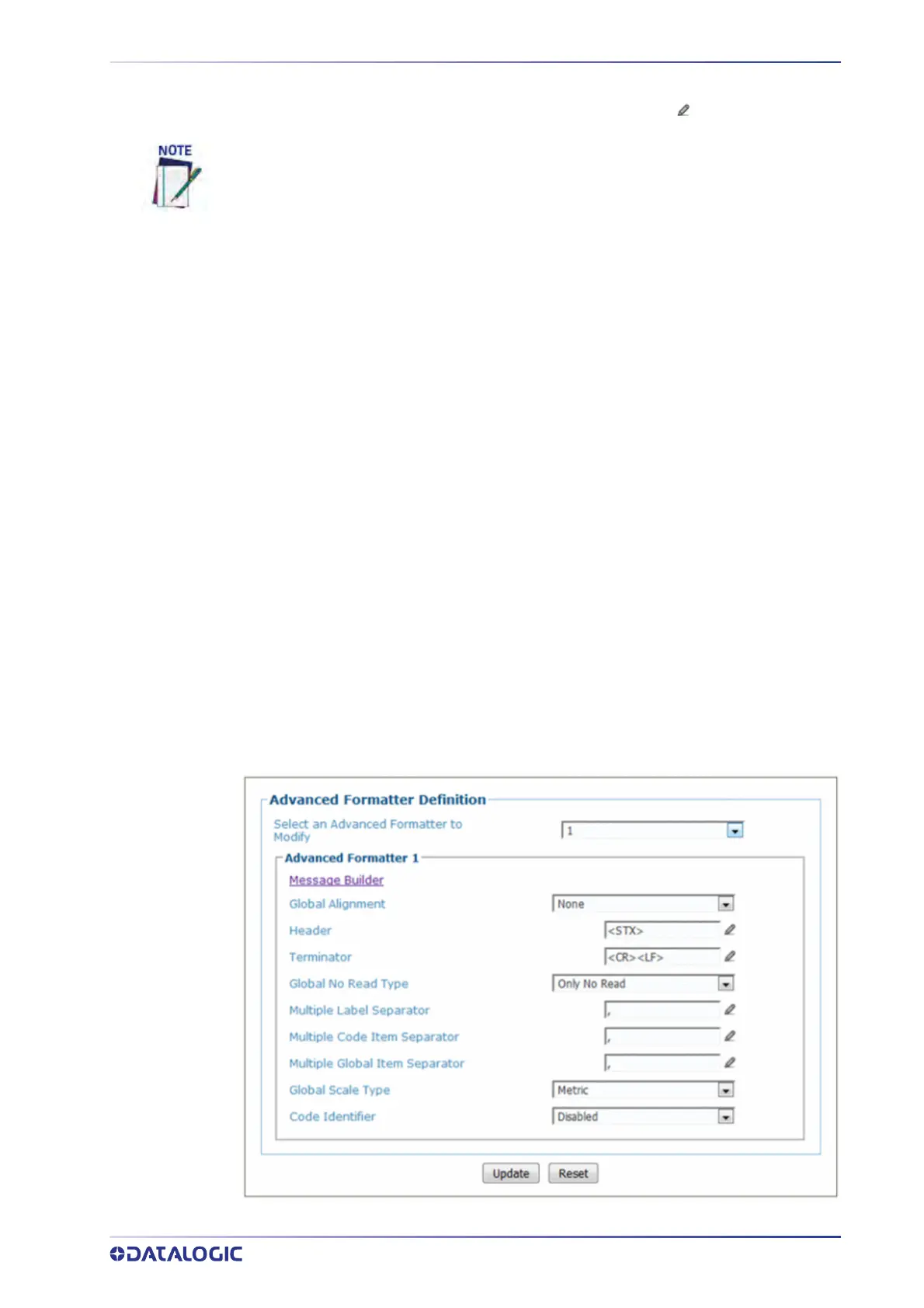
Configuration Host Message with Protocol Index
Navigate to Modify Settings | Global Settings | Output Format | Advanced Formatter.
the Advanced formatter window opens
The header and terminator must match the Protocol Index source, in this case, the
scale structures.