ELECTRICAL INSTALLATION
76
AV500/AV900 2D CAMERA
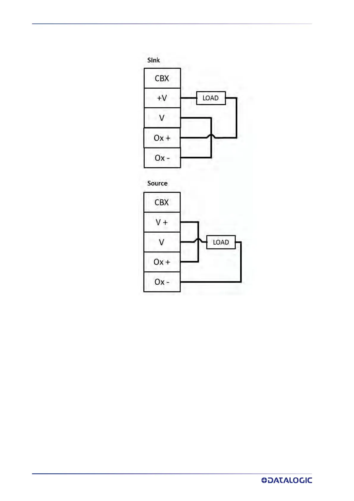
Powered Outputs
Grounding
To avoid any problems with electrical noise that could negatively affect system function,
make sure that:
1. The AC power cable coming into the PWR box is always provided with a Ground
and conn
ected to the proper connector (Protective Earth - PE).
2. The structure where the readers, controllers, encoders/tachometers, and photo-
electric sensors are mounted is grounded to the conveyor or to the PE terminal
insi
de the PWR.
3. The Shield
wires from the Encoder/Tachometer and photoelectric sensor cables
are connect
ed to the proper Shield terminal in the CBX box.
4. Normally, steps 1 through 3 will guarantee proper function. In case of problems
such as transmission of s
trange or wrong characters, devices stop working without
any reason, or other unexpected behavior, try connecting the CBX or Controller
Earth terminal to the PE terminal inside the PWR box.