CONNECTOR PANEL
PRODUCT REFERENCE GUIDE
51
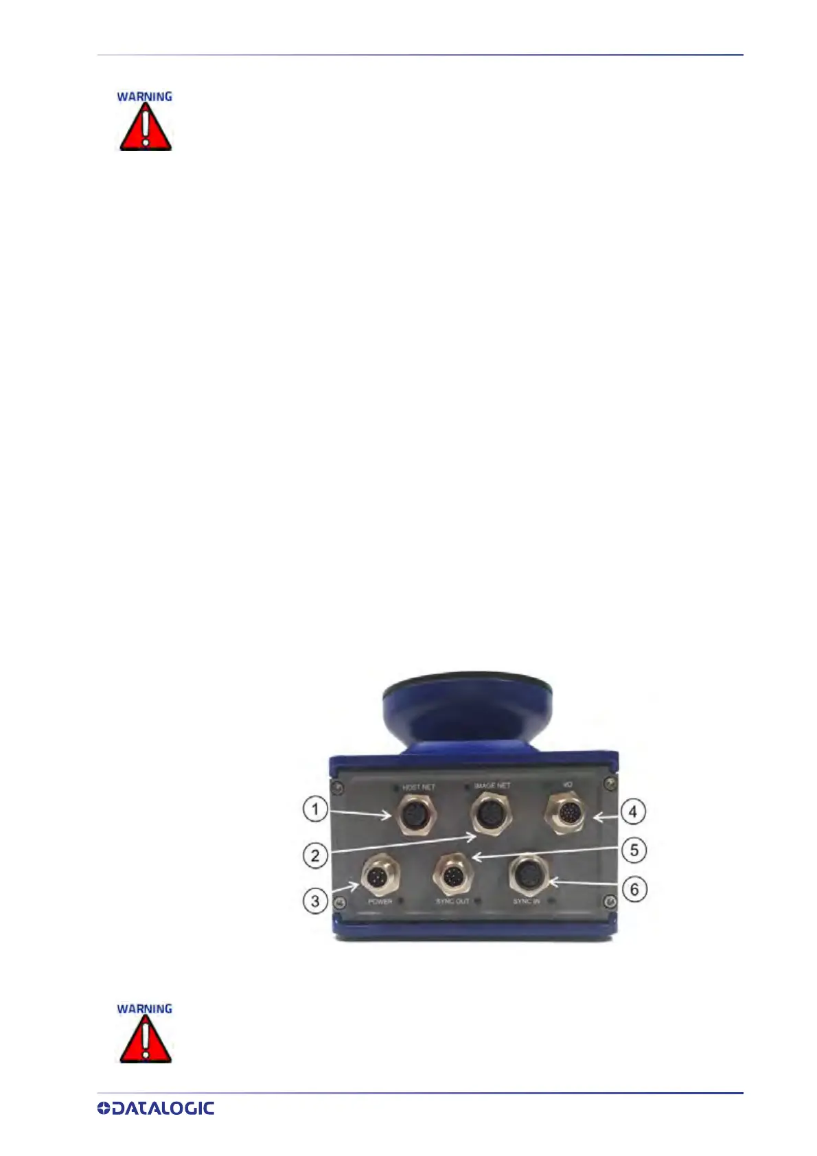
CONNECTOR PANEL
After completing mechanical installation, use this section to properly wire your cameras
for optimal performance in your application. AV500/AV900 wiring connections are
made to the connector panel and through the CBX connection box (via the AV500/
AV900 I/O port). In most applications, the cable connections to the barcode reader will
include:
1. HOST NET – B
arcode data to Host
2. IMAGE NET – Conf
iguration, Remote Monitor application or image export
3. POWER – Po
wer connected to AV500/AV900 power connector
4. I/O – Provides connection to CBX Connection Box
5. SYNC OUT – AV500/
AV900 internal data, device network
6. SYNC IN – AV50
0/AV900 internal data, device network
When planning your installation wiring, remember all power connections must be quick-dis-
connect. For PERMANENTLY CONNECTED EQUIPMENT a readily accessible disconnect device
must be incorporated in the building installation wiring. For PLUGGABLE EQUIPMENT the
socket-outlet must be installed near the equipment and must be easily accessible.
To assure no ESD damage will occur, be sure to observe the precautions outlined in the
Introduction to this manual.
Ground the mounting structure to safety ground (protective earth ground (PE)). See section
“Grounding” on page 76 for wiring recommendations for safety ground.
If a connector is not in use, it should always be covered with its protective cap.