ELECTRICAL INSTALLATION
52
AV500/AV900 2D CAMERA
Route wiring from the barcode reader’s connector panel through the wiring channels (if
available) on the Datalogic mounting structure when interconnecting cables to other
devices.
CONNECTING A PC TO THE AV500/AV900
During initial setup, a PC (laptop) may be connected to the AV500/AV900 with an RJ45
cable. Connect an Ethernet cable from the HOST NET or IMAGE NET port of the AV500/
AV900 to the Ethernet port of your PC. For information on connecting to e-Genius, see
“Accessing e-Genius” on page 79.
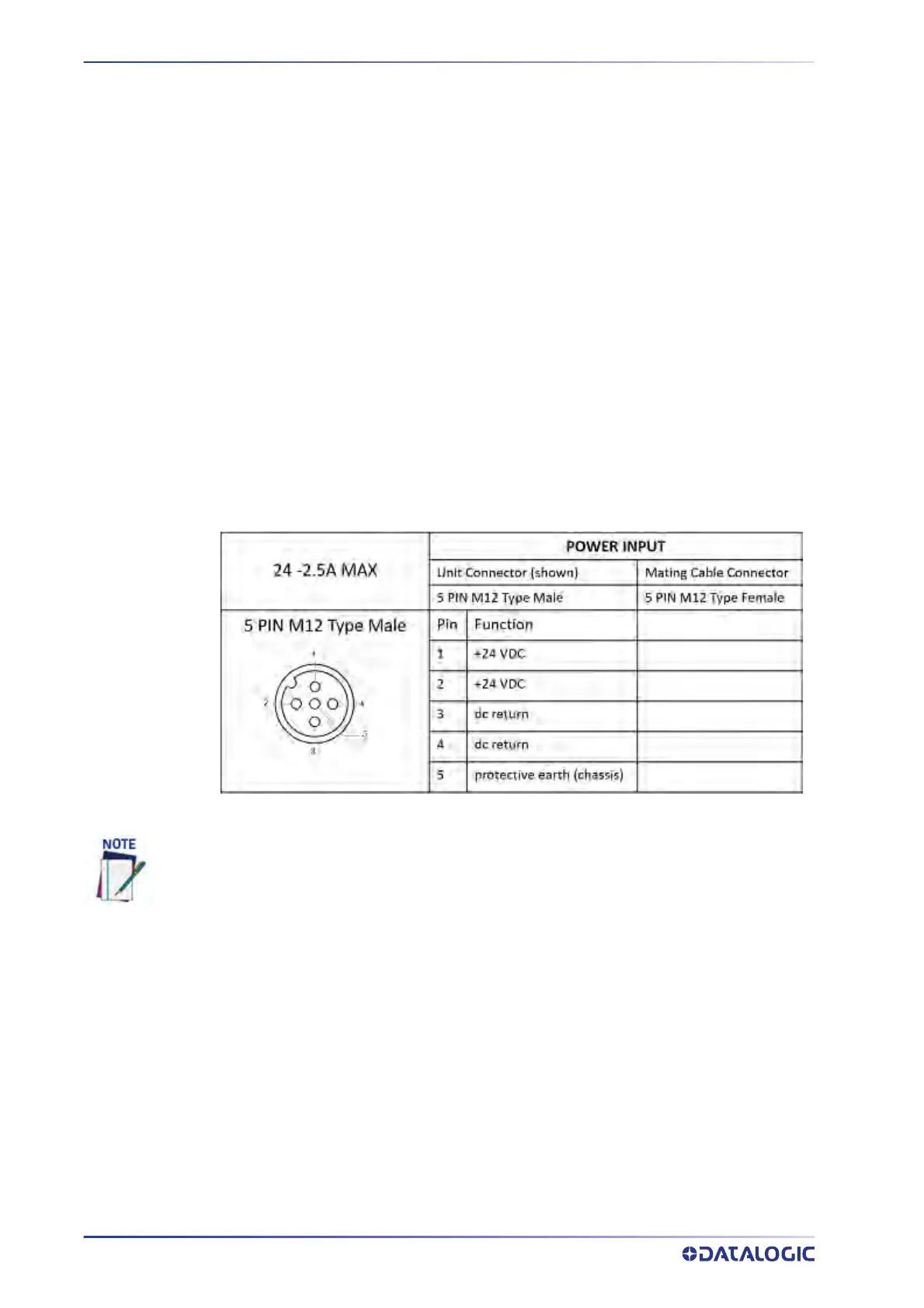
POWER CONNECTOR PIN-OUT TABLE (CUSTOM POWER
SUPPLY)
A recommended power supply and cabling is available for the AV500/AV900 Camera.
However, if your installation requires custom power supply wiring, the pin-outs of the
AV500/AV900 camera power connector are provided below.
SELECTING THE CORRECT CBX CONNECTION BOX FOR YOUR
APPLICATION
As shown in section “Standard Interconnection Diagrams INTRODUCTION” on page 329,
typical applications require a single CBX connection box to connect the trigger and
enco
der inputs to the master camera. The camera sources power to these devices.
Other possible CBX connections are for digital outputs or a serial host.
• CBX100 - used for sla
ve cameras (and as an alternative for master cameras). It pro-
vides general access to digital input/output signals.
When using an AV500/AV900 camera, no power supply is required for the CBX510 connec-
tion box. All power and some communication options are fed to the CBX510 through the
scanner’s 17-pin I/O connector to the CBX510 25-pin connector using the cable provided.
In cases where the AS-I cabling is not used, the alternative CAB-LP-05 cable can be used to
connect the power supply to the scanner. Connect the Brown/White pair to +24 Vdc and the
Blue/Black pair to dc return.