GENERAL VIEW
PRODUCT REFERENCE GUIDE
3
Industrial Strength
• Industrial compact 2D reader
• Rugged full metal construction
• Sealed circular connectors
• IP65 protection class
• 50 °C max operating temperature
• Supply voltage ranges 24 VDC Nominal, +/-20%
This chapter introduces the basic concepts necessary for camera installation and setup.
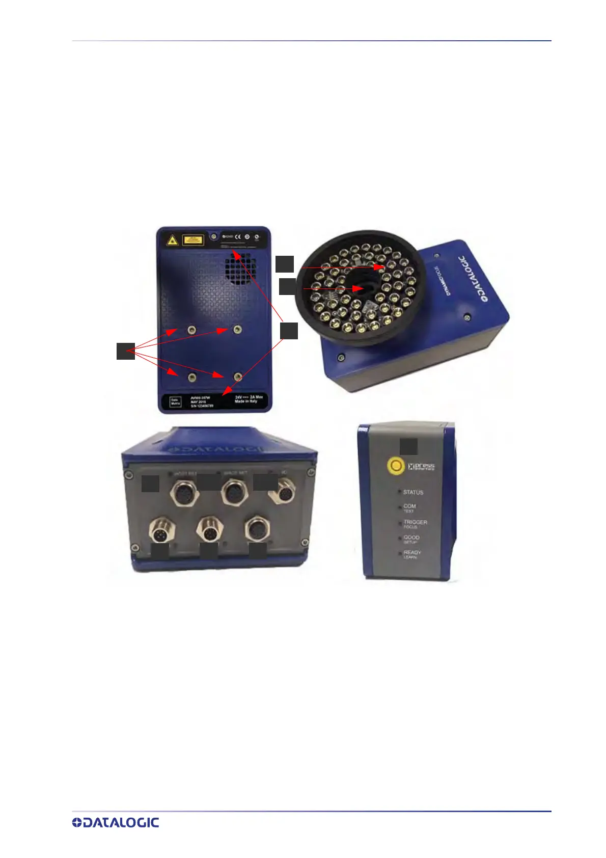
GENERAL VIEW
1 Serial Number and Warning Labels
2 Bracket Mounting Holes
3 Lens and Green Spot LED
4 Illumination
5 HMI X-Press Interface
6 Power On Connector and LED - stays blue when receiving power
7 Sync Out Connector and LED - flashes orange
8 Sync In Connector and LED - flashes orange
9 Host Net Connector and LED - lashes green and orange, orange if receiving data
10 Image Net Connector and LED - flashes green and orange, orange if receiving data
11
I/O Connector and LED - will l
ight when connected to the CBX box