APPENDIX B
340
AV500/AV900 2D CAMERA
I/O CONTROLLOGIX MESSAGING EXAMPLE
The following example illustrates how a camera can be configured to communicate with
a ControlLogix processor using I/O messaging.
Using this information along with the
Reader Object definitions later in this document, it should be possible to adapt these
directions for other EtherNet/IP network master devices.
When EtherNet/IP is enabled on the camera, EIP I/O Messaging is automatically
enabled. No further configuration on the Datalogic device is needed to setup I/O mes-
saging. Since the ControlLogix processor now treats the c
amera as an I/O device, to
setup an EIP I/O message transfer between a camera and a ControlLogix processor, you
need to configure your camera as a Generic Ethernet Module in the ControlLogix I/O
tree.
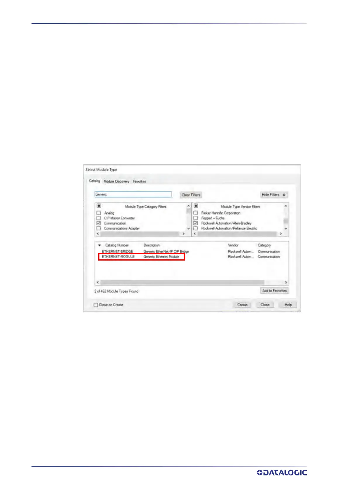
Follow these steps to add a module:
Right click and select New Module on the entry f
or your Ethernet module under the I/O
Configuration Tree. A list of options similar to what is shown below will appear.
1. From this list select ETHERNET-MODULE for th
e Generic Ethernet Module.
2. Click OK.