Virtual Router Redundancy Protocol (VRRP) | 1149
VRRP in VRF Configuration
The example in this section shows how to enable VRRP operation in a VRF virtualized network for the
following scenarios:
• Multiple VRFs on physical interfaces running VRRP
• Multiple VRFs on VLAN interfaces running VRRP
To view a VRRP in VRF configuration, use the
show commands described in Displaying a VRRP in VRF
Configuration on page 1154.
Non-VLAN Scenario
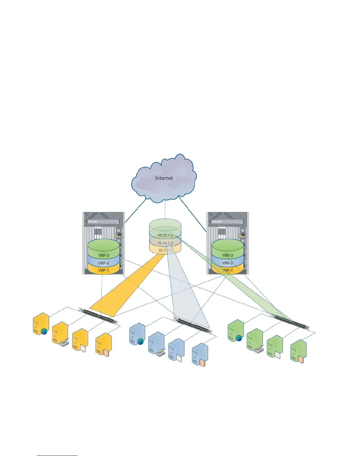
Figure 58-25. VRRP in VRF: Non-VLAN Example
Figure 58-25 shows a typical use case in which three virtualized overlay networks are created by
configuring three VRFs in two E-Series switches. The default gateway to reach the internet in each VRF is
a static route with the next hop being the virtual IP address configured in VRRP. In this scenario, a single
VLAN is associated with each VRF.
Switch-1
VRID 11
Node IP 10.10.1.5
Virtual IP 10.10.1.2
VRID 11
Node IP 10.10.1.6
Virtual IP 10.10.1.2
VRID 15
Node IP 20.1.1.5
Virtual IP 20.1.1.5
Switch-2
VRID 11
Node IP 10.10.1.2
Virtual IP 10.10.1.2
VRID 11
Node IP 10.10.1.2
Virtual IP 10.10.1.2
VRID 15
Node IP 20.1.1.6
Virtual IP 20.1.1.5

 Loading...


