Link Aggregation Control Protocol | 547
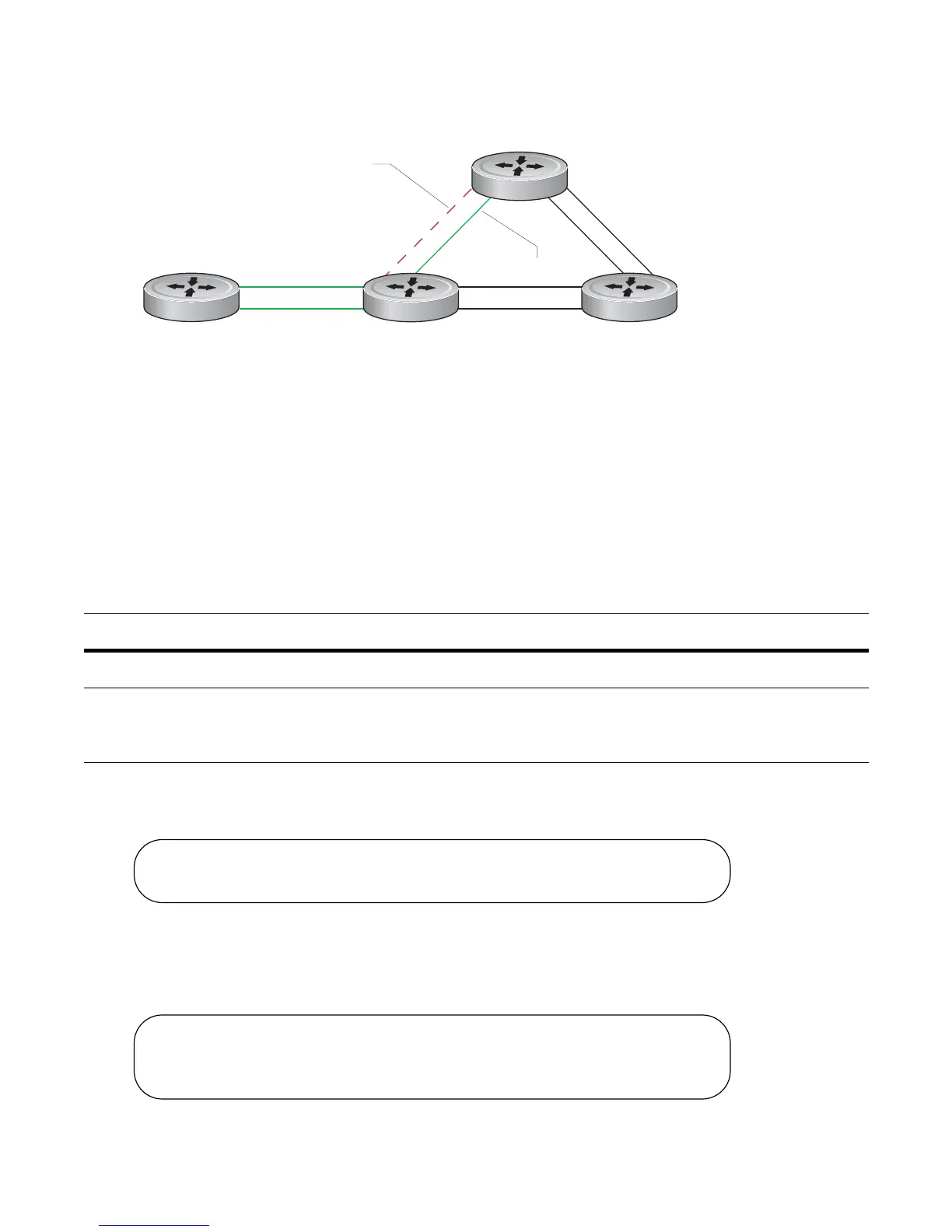
Figure 24-5. LAGs using ECMP without Shared LAG State Tracking
To avoid packet loss, traffic must be re-directed through the next lowest-cost link (R3 to R4). FTOS has the
ability to bring LAG 2 down in the event that LAG 1 fails, so that traffic can be re-directed, as described.
This is what is meant by Shared LAG State Tracking. To achieve this functionality, you must group LAG 1
and LAG 2 into a single entity, called a failover group.
Configure Shared LAG State Tracking
To configure Shared LAG State Tracking, you configure a failover group:
In Figure 24-6, LAGs 1 and 2 have been placed into to the same failover group.
Figure 24-6. Configuring Shared LAG State Tracking
View the failover group configuration using the show running-configuration po-failover-group
command, as shown in Figure 24-7.
Figure 24-7. Viewing Shared LAG State Tracking in the Running-configuration
Step Task Command Command Mode
1
Enter port-channel failover group mode.
port-channel failover-group
CONFIGURATION
2
Create a failover group and specify the
two port-channels that will be members
of the group.
group number port-channel
number port-channel number
CONFIG-PO-FAILOVER-GRP
Po 1
Po 2
fnC0049mp
R1
R2 R3
R4
Po 1 failure
Po 2 over-subscribed
R2#config
R2(conf)#port-channel failover-group
R2(conf-po-failover-grp)#group 1 port-channel 1 port-channel 2
R2#show running-config po-failover-group
!
port-channel failover-group
group 1 port-channel 1 port-channel 2

 Loading...


