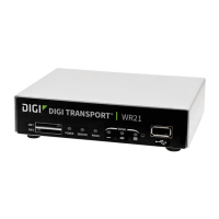
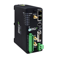
Hardware TransPort WR21 hardware
Digi TransPort WR Routers User Guide 38
TransPort WR21 serial pinout
Note that all TransPort serial ports are DCE.
RS232 pinout
RS422/ RS485 pinout
Notes
▪ For true RS485 mode (2-wire half-duplex mode), the TD+ and RD+ pair and TD- and RD- pair
should be connected together.
▪ The CTS and RTS signals are optional and not normally needed for RS485.
Pin # Direction RS232 DCE Description
1 Out DCD Data Carrier Detect
2 Out RXD Receive Data
3In TXD Transmit Data
4 In DTR Data Terminal Ready
5N/A GND Ground
6 Out DSR Data Set Ready
7In RTS Ready To Send
8Out CTS Clear To Send
9 Out RI Ring Indicate
Pin # Direction RS422/ RS485 Description
1 Out CTS- Clear To Send -
2 Out RD+ Receive Data +
3 In TD+ Transmit Data +
4 In RTS_B RTS- Ready To Send -
5N/A GND Ground
6 Out RD- Receive Data -
7In RTS+ Ready To Send +
8 Out CTS+ Clear To Send +
9 In TD- Transmit -
WWAN
SECONDARY
SERIAL 0
9-30VDC
2A MAX
WWAN
PRIMARY
LAN 1LAN 0
SERIAL 0
Pin 1
Pin 9
 Loading...