112
z Exterior
chap.3
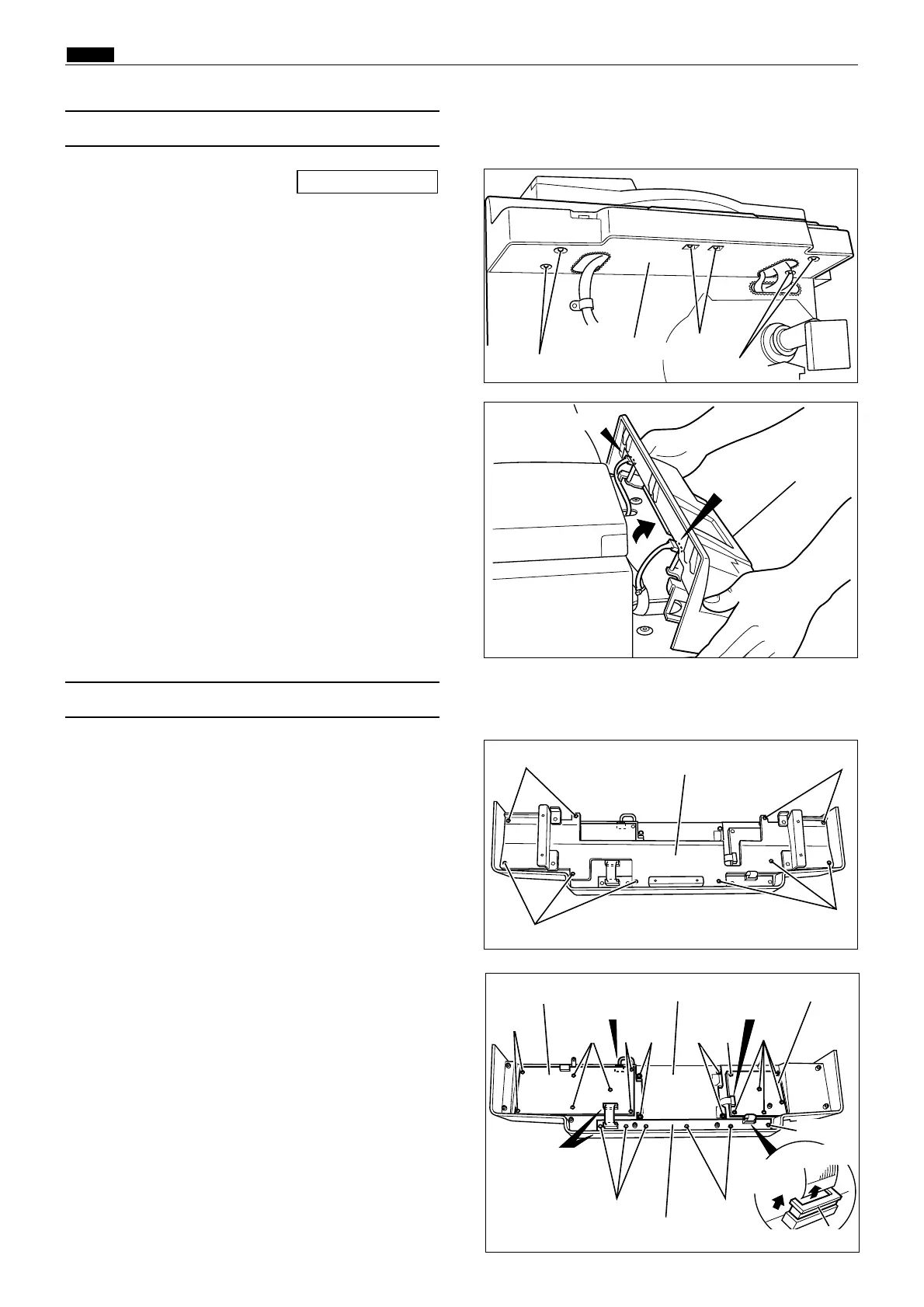
1) Remove the preciously mentioned (2) and (6).
and detach the LCD code.
2) Remove the 10 screws indicated, then remove
the bracket.
(7) Removal of Control Panel PCB
440107
Screws
Screws
Bracket
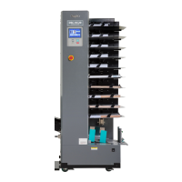
1) Remove the front cover.
\See page 108
(6) Removal of Control Panel
3) Remove the control panel by pulling up.
4) Remove the 2 connectors.
440040
2) Remove the 6 screws.
Screws
Control panel
Screws
440106
Control panel
Connector
Connector
440108
Screws
Screws
Connector
Panel board C
3) Follow the instructions below to remove.
¡ Panel board A
(2 connectors, 7 screws)
¡ Panel board B
(2 connectors, 6 screws)
Pull the sliding stopper on the connector terminal
upwards to release it, then pull out the LCD cable.
¡ Panel board C
(2 connectors, 6 screws)
Pull the sliding stopper on the connector terminal
upwards to release it, then pull out the LCD cable.
¡ LCD Panel
(2 connectors, 4 screws)
Screws
Screws
Panel board B
Panel board A
LCD panel
Connector
Connector
Screws Screws Screws
Screws
Screw
Sliding stopper
Screws
qPull
upwards
wPull out
Screws