135
n Paper Ejection Section
chap.3
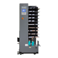
(3) Removal of Paper Ejection Fan Unit
1) Remove the print tray.
2) Remove the 2 screws from the cover, and remove
the cover.
3) Disconnect the 4 connectors.
4) Remove the 2 screws, and pull out the paper
ejection fan unit sliding in the direction of an
arrow.
440152
440080
440081
Cover
Screw
Screw
Paper ejection fan unit
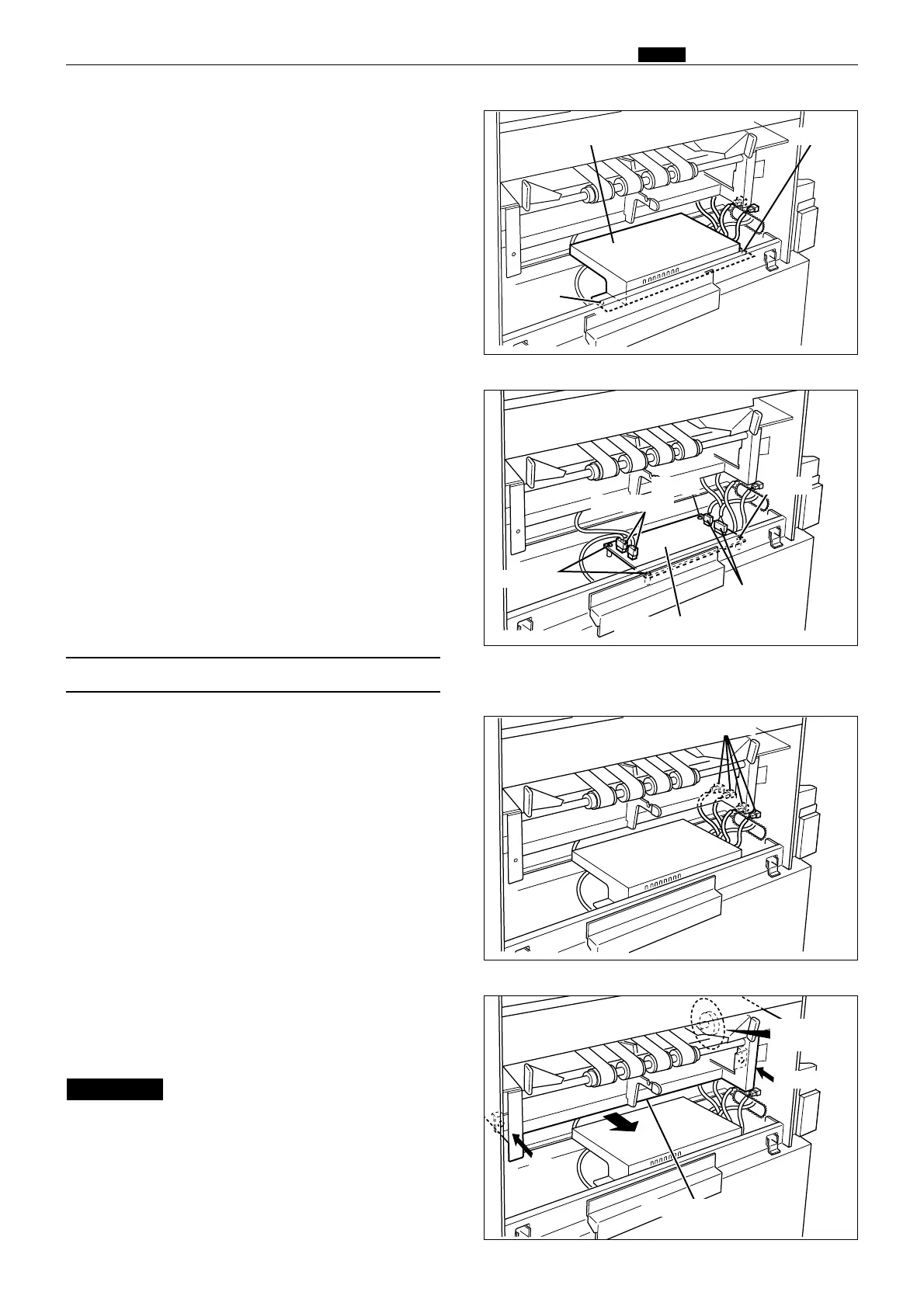
3) Remove the 3 screws indicated, and remove the
cover.
440079
Main motor PCB unit
Screws
Connectors
Connectors
Screw Screw
Screw
Connectors
Screw
When pulling out the paper ejection
fun unit, do not entangle the encoder.
IMPORTANT :
Do not entangle
the encoder
4) Disconnect the 4 connectors.
5) Remove the 4 screws indicated, and remove the
main motor PCB unit.