130
v Paper Feed Section
chap.3
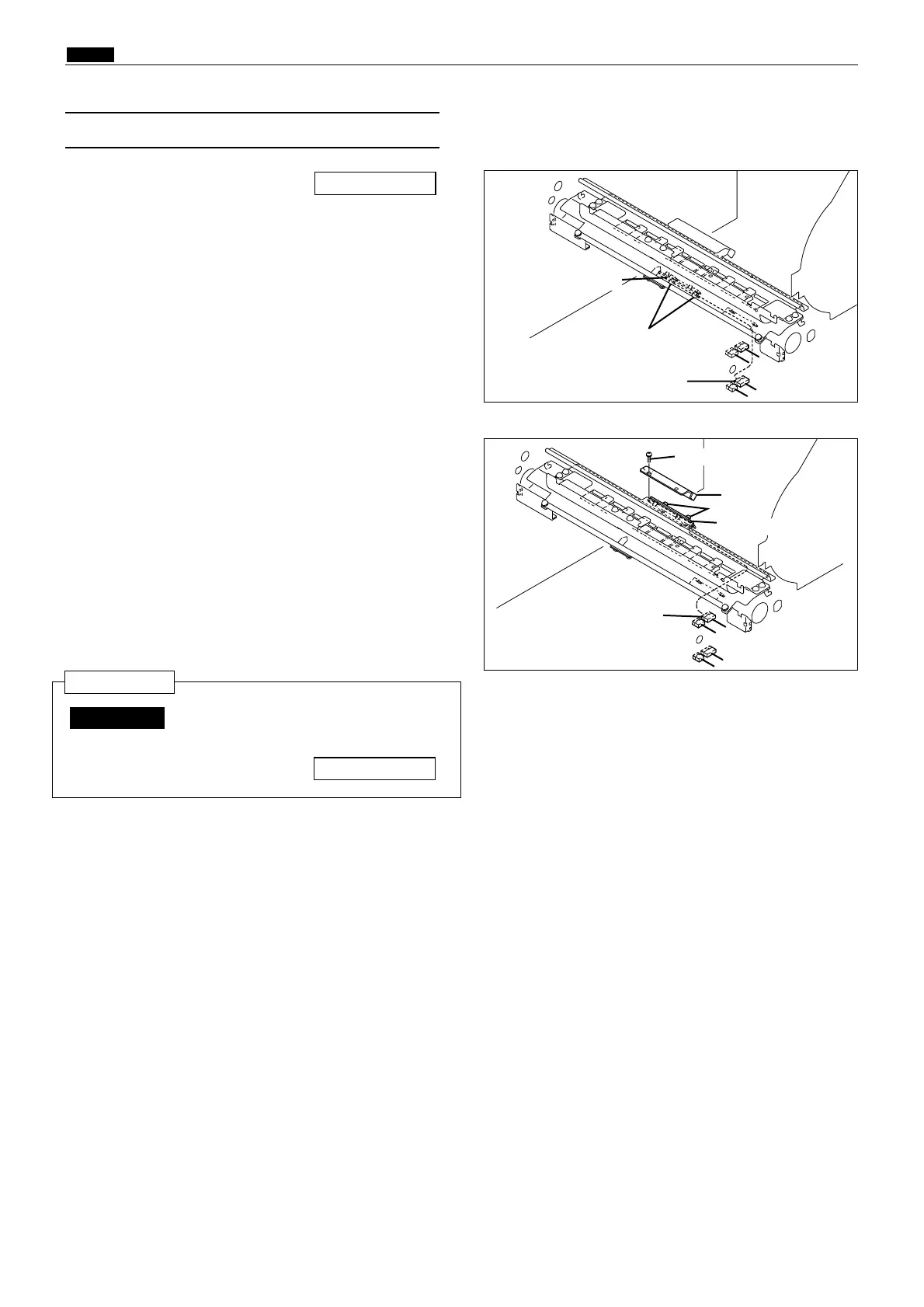
1) Remove the paper feed unit.
2) Disconnect the 2 connectors.
3) Remove the 2 screws indicated, then remove the
photo-emitting PCB sensor.
\See page 129
(7)
Removal of Double Feed Detection Sensor
After reinstalling the double feed
detection sensor, carry out adjustment
of its sensitivity.
\See page 161
IMPORTANT :
Reinstallation
440146
Screws
Connector
Photo-emitting PCB
440147
Screws
Photo-receiving PCB
Connector
4) Remove the drum unit.
5) Remove the 2 screws indicated, then remove the
cover.
6) Remove the 2 screws indicated, then remove the
photo-receiving PCB sensor.
Screw
Cover