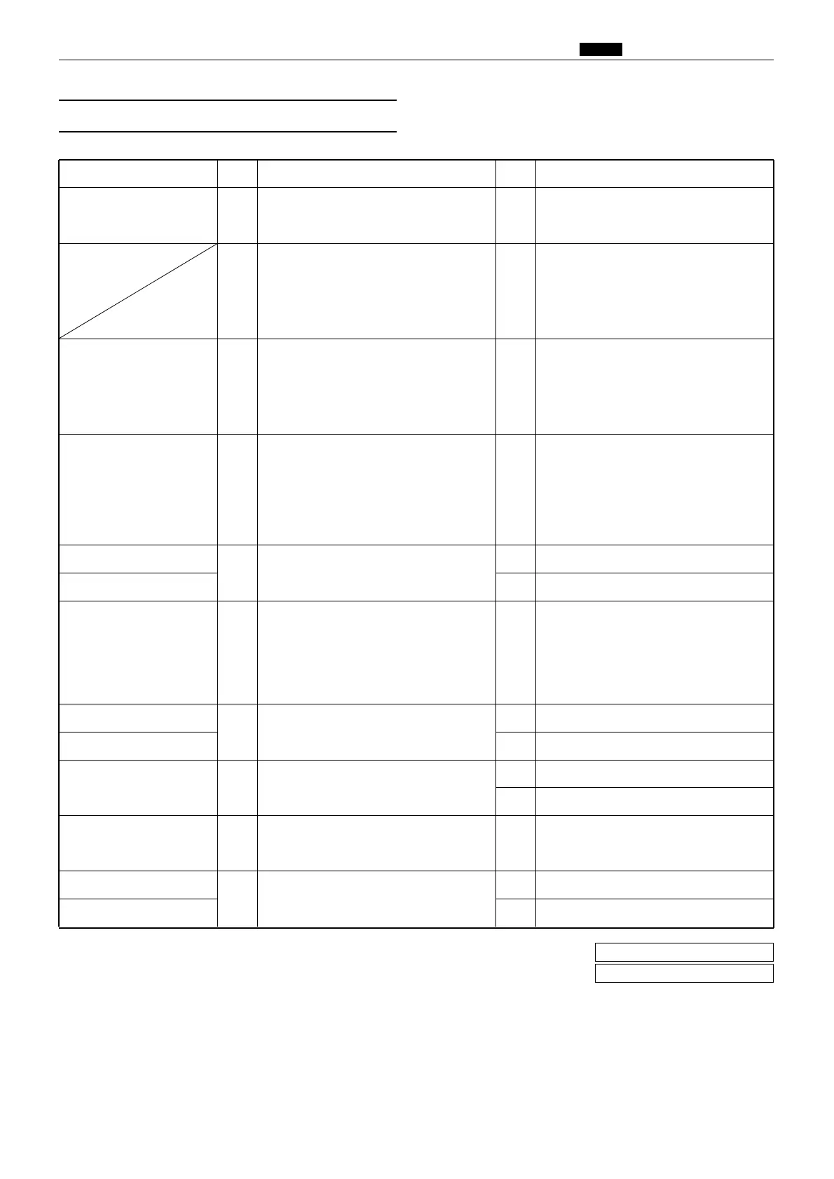
Cause/Detective section
Procedures
Result
CountermeasureItems to be checked
Feed tray operation is
defective
1
Does the feed tray operate smoothly
when moved up/down by hand?
YES
Remove the cause of defective operation.
Lean or catch?
2
Check with the HELP modes, H-05, H-
07. Are the elevator top limit sensor
and the elevator bottom limit switch
noraml?
NO
• Follow the procedure
7
when the
elevator top limit sensor is defective.
• Follow the procedure
10
when the
elevator bottom limit sensor is defective.
Regulated power supply
3
Remove the drive PCB Unit CN5.
Measure the voltage between the regu-
lated power supply, +S(+24), -S (GND)
with the tester. Is the voltage +24 V?
NO Replace the regulated power supply.
Elevator motor
4
Measure the voltage between the main
PCB Unit CN8-4 (+) and CN8-3 (-) with
the tester at the timing of the elevator
motor operation. Is the voltage +24V
whether the elevator motor relay con-
nector is inserted or not?
YES Replace the elevator motor.
Drive PCB Unit
5
Is the cause cleared by replacing the
drive PCB Unit?
YES Finish.
Elevator motor NO Replace the elevator motor.
Main PCB Unit
6
Measure the voltage between the main
PCB Unit CN1-6 (+) and GND with the
tester. Is the voltage of the elevator top
limit sensor 0V at the time of pho-
topassing and 5V at the time of pho-
tointerrupting?
YES Replace the main PCB Unit.
Main PCB Unit
7
Measure the voltage between the main
PCB Unit CN1-6 (+) and CN1-1 (GND)
with the tester. Is the voltage +5V?
NO Replace the main PCB Unit.
Elevator top limit sensor YES Replace the elevator top limit sensor.
8
Measure the voltage between the DC-
DC PCB Unit CN4-1 (GND) and CN4-6
(+) with the tester. Is the voltage +5V?
YES Replace the DC-DC PCB Unit.
DC-DC PCB Unit
NO Follow the procedure
9
.
9
Measure the voltage between the regulated
power supply,CN1-1(GND) and CN1-
3(+) with the tester. Is it +24V?
Regulated power supply
NO
Replace the regulated power supply.
Elevator bottom limit SW
10
Check the elevator bottom limit switch
with the tester. Is the switch turned on
or off normally?
NO Replace the elevator bottom limit SW.
Main PCB Unit YES Replace the main PCB Unit.