137
n Paper Ejection Section
chap.3
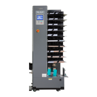
1) Open the top blow fan cover.
2) Remove the 2 screws indicated, then remove the
cover.
(6) Removal of Top Blow Fan Unit
440153
Screws
Cover
Top blow fan cover
440154
loosen
3) Disconnect the 3 connectors.
4)
Loosen the screw and remove the screw indicated,
then remove the top blow fan unit.
remove
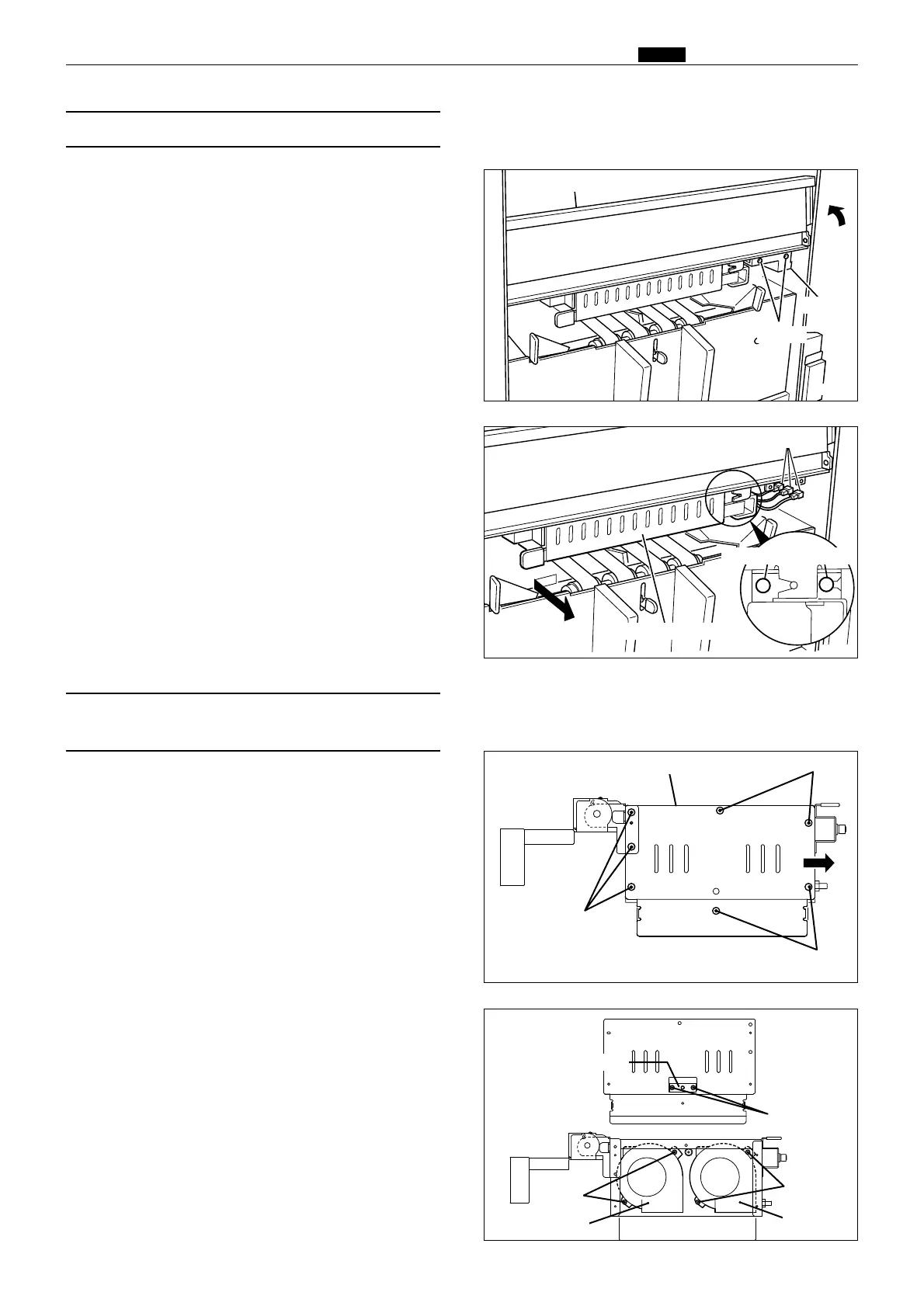
1) Remove the top blow fan unit.
2) Remove the 7 screws indicated, and remove the
cover sliding in the direction of an arrow.
(7) Removal of Fan/Jam Sensor
(Photo-emitting PCB Unit)
440155
Screws
Fan cover under unit
440156
Screws
Photo-emitting PCB
3) Remove the 2 screws indicated, then remove the
fan / photo-emitting PCB sensor.
Fan
Screws
Screws
Screws
Screws
Fan
Top blow fan unit
Connectors