136
n Paper Ejection Section
chap.3
440083
440082
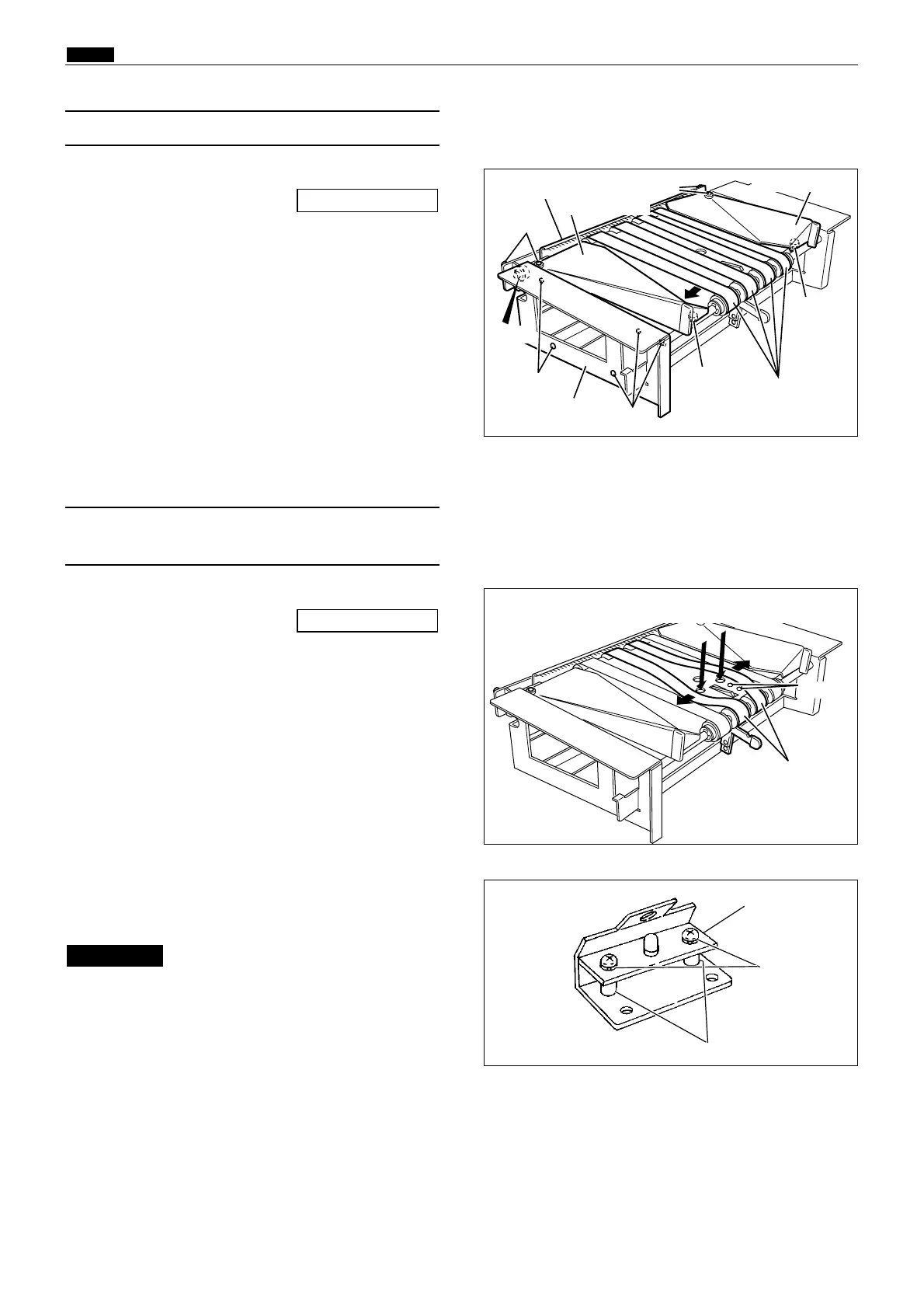
1) Remove the paper ejection fan unit.
2) Pull the paper ejection belts wider apart to
expose the screws, and secure the belts in that
position.
3) Remove the 2 screws indicated, and remove the
paper aligning lever assy.
4) Remove the 2 screws securing the sensor
mounting angle, and remove the angle.
\See page 135
5) Remove the 2 screws from the sensor PCB, and
remove the PCB.
Do not lose the 2 spacers.
IMPORTANT :
Remove the 2 screws with a driver
Paper ejection belts
Paper ejection JAM
sensor
Screws
Spacers
(5) Removal of Paper Ejection JAM Sensor
(Photo-receiving
PCB UNIT)
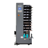
(4) Removal of Paper Ejection Belt
1) Remove the paper ejection fan unit.
2) Remove the 2 screws from the static removal
brush, and remove the static removal brush.
\See page 135
3) Remove the 4 screws indicated, and remove the
jump base L,R.
4) Remove the 5 screws indicated, and remove the
frame L.
5) Remove the E-ring.
6) Stretch the belts and install them oriented as
shown in the figure.
Screw
Paper ejection belts
Frame L
Static removal brush
Screws
E-ring
Screws
Screws
Screw
Jump base L
Jump base R
Screws
Screws