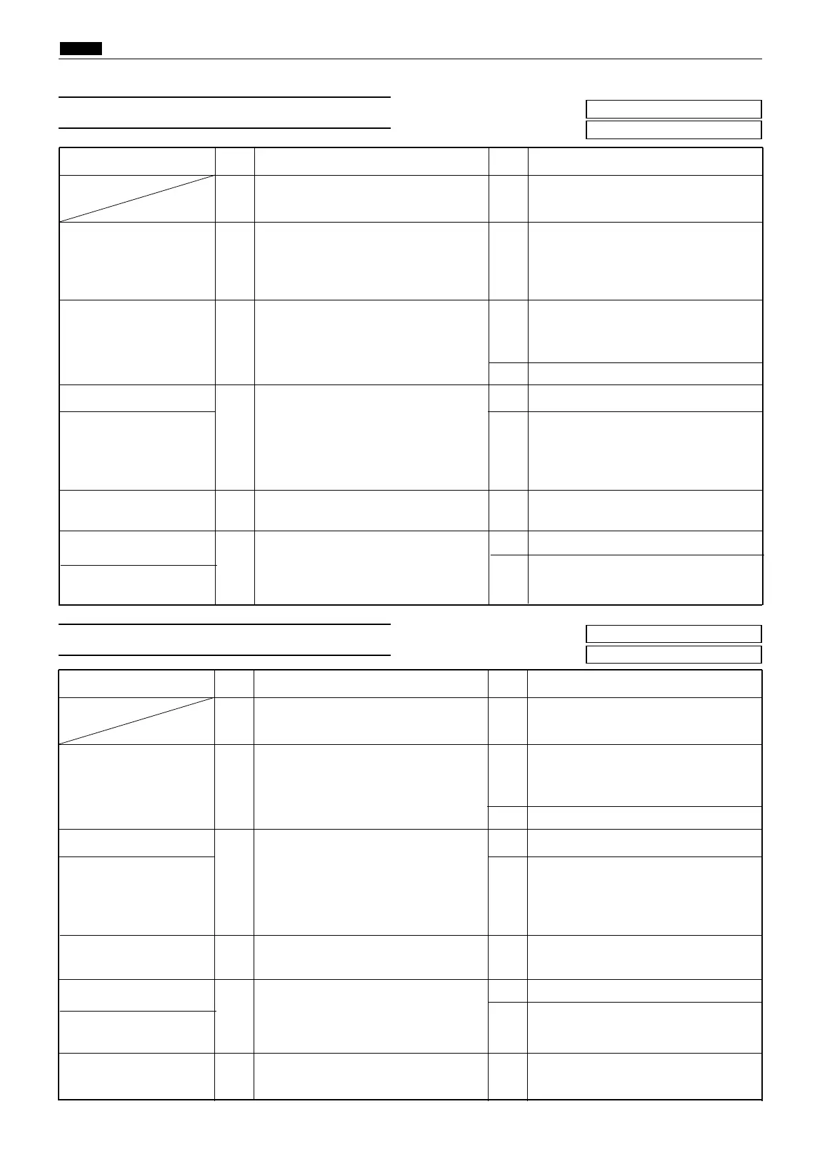
Cause/Detective section
Procedures
Result
CountermeasureItems to be checked
1
Does thermal head up/down motor turn
when it is checked using HELP02*?
YES Follow the procedure
5
.
Thermal head up/down
motor
2
Using a tester, measure the voltage
between CN14-9 (+) and CN14-10 (GND)
when the thermal head up/down motor
is activated using HELP02*. Is it +24V?
YES
Check the bundled wire. If OK, replace
the thermal head up/down motor.
Regulated power supply
3
Drive PCB unit
4
Does replacing the drive PCB unit solve
the problem?
YES Finish.
Main PCB
NO
Check the connector and bundled wire
between the drive PCB unit CN1 and
the main PCB CN3. If OK, replace the
main PCB unit.
Thermal head position
sensor position
5
Does the thermal head position sensor sta-
tus when it is checked using HELP05**?
YES
Adjust the thermal head position sensor.
Measure the voltage between the regulated
power supply, +S (+24) and -S(GND)
with the tester. Is it +24V?
NO
Measure the voltage between L and N of the
regulated power supply with the tester. If it is
100V, replace the regulated power supply.
Follow the procedure
4
.
YES
Thermal head position
sensor
6
Turn the thermal head position sensor
on and off, and use a tester to measure
voltage. Is voltage normal?
NO Replace thermal head position sensor.
Main PCB Unit
YES
Check the bundled wire. If OK, replace
the main PCB unit.
Replace scanner home position sensor.
Cause/Detective section
Procedures
Result
CountermeasureItems to be checked
1
Does scanner stepping motor turn
when it is checked using HELP10*?
YES Follow the procedure
5
.
Regulated power supply
2
Drive PCB unit
3
Does replacing the drive PCB unit solve
the problem?
YES
Finish.
Main PCB Unit
NO
Check the connector and bundled wire
between the drive PCB unit CN1 and
the main PCB CN3. If OK, replace the
main PCB unit.
Scanner stepping motor
6
Does replacing the scanner stepping
motor solve the problem?
YES
Finish.
Measure the voltage between the regulated
power supply, +S (+24) and -S(GND)
with the tester. Is it +24V?
NO
Measure the voltage between L and N of the
regulated power supply with the tester. If it is
100V, replace the regulated power supply.
Follow the procedure
3
.
YES
Scanner home position
sensor
5
Turn the scanner home position sensor
on and off, and use a tester to measure
voltage. Is voltage normal?
NO
Main PCB Unit
YES
Check the bundled wire. If OK, replace
the main PCB unit.
Scanner home position
sensor position
4
Does the scanner home position sensor sta-
tus when it is checked using HELP05**?
YES
Adjust the scanner home position sensor.