36
z Scanner Section
chap.2
3. Function of Parts and Circuit
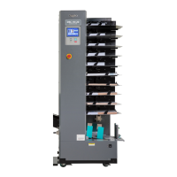
(1) Home Position Sensors
Description
PS1 detects the optical system home position when ADF is not used.
PS2 detects the optical system home position when ADF is used.
Scanner home position sensor (PS1)
Main PCB unit
Red
Blue
CN11-11
2
3
1
2
3
-3
Yellow
Red
Blue
Yellow
-2
5V
5V
5V
0
Photopassing :0V
Photointerrupting:5V
Circuit
Operation
23S0214
440W01e
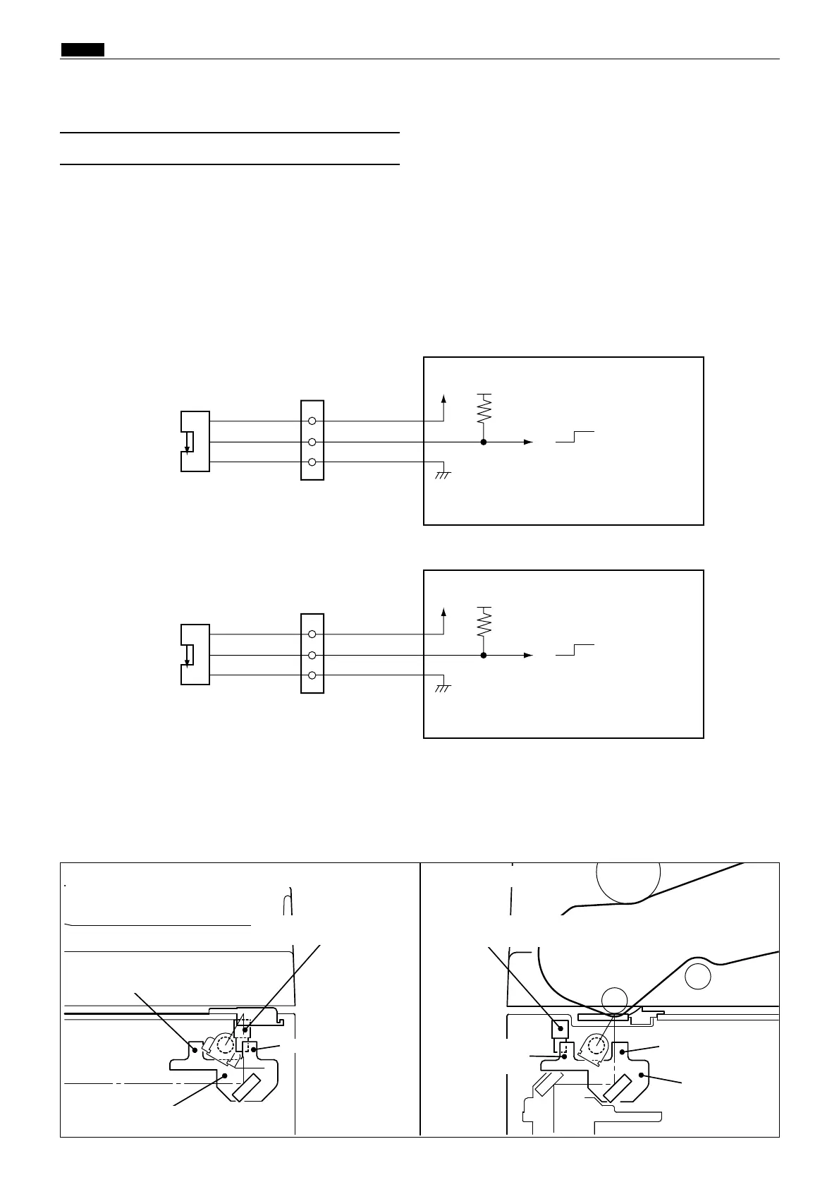
Photointerrupting plate
Slider A
Scanner
home position sensor(PS1)
ADF
home position sensor(PS2)
Slider A
Photointerrupting plate
Photointerrupting
plate
Photointerrupting
plate
A shading plate is attached on slider A of the optical system. The position where PS1 is shaded becomes the
optical system home position when ADF is not attached.
The position where PS2 is shaded becomes the optical system home position when ADF is attached.
ADF home position sensor (PS2)
Red
Blue
CN11-41
2
3
4
5
6
-6
Orange
Red
Blue
Orange
-5
5V
5V
5V
0
Main PCB unit
Photopassing :0V
Photointerrupting:5V
440W02e
• Standard (ADF not attached) • With ADF attached