X-STREAM
2-7
Instruction Manual
HASAxE-IM-HS
05/2006
Emerson Process Management GmbH & Co. OHG
2 Technical Data
2-2-1 X-STREAM GP, X-STREAM GPS
Signal inputs / outputs
All signal lines need to be connected to screw
terminals located at the analyzer‘s rear panel.
Available signals: standard: Analog signal outputs
Relay status signals
Modbus interface (RS232; RS 485)
optional: Digital inputs/outputs
Detailed pin assignment
4-4 Installation, page 4-6.
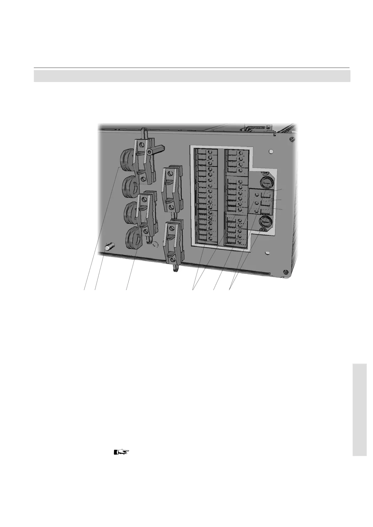
Fig. 2-2: X-STREAM GP, (terminals version) -
terminals and fuse holders (cover removed)
1 Fuse holders
2 Power terminals
3 Signal terminals
4 Strain reliefs
5 Protective earth terminal (PE)
6 Edge protection (part of removed cover;
shown for demonstration only)
64 3125
Line
PE
Neutral
 Loading...


