X-STREAM
4-15
Instruction Manual
HASAxE-IM-HS
07/2006
Emerson Process Management GmbH & Co. OHG
4 Installation
Modbus interface
Specification and driving the interface:
Chapter 9
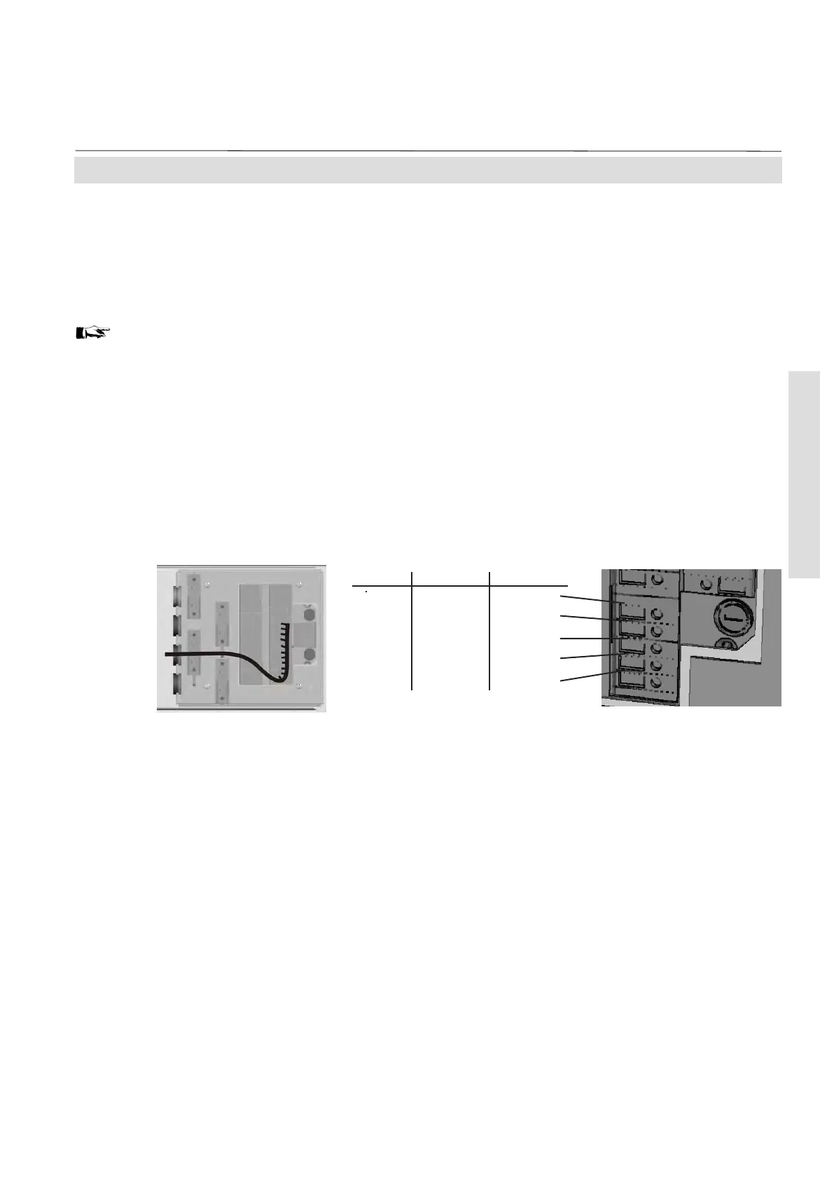
The lower 5 terminals (# 11 - 15) of the terminals
row next to the power terminals are reserved
for the Modbus interface (left side of figure
shows a combined cable carrying RS and relay
contact signals).
To connect the terminals remove the cover at
the analyzer's rear panel (4 screws). Feed the
serial signal cable through the 3
rd
edge
protection, and through the 3
rd
strain-relief.
Note 1!
Take care of the special installation
instructions in section 4-5!
4-4-1 Installation - X-STREAM GP, X-STREAM GPS
Fig. 4-12: Modbus Interface Terminals
Note 2!
X-STREAM analyzers are to be considered
a DTE (Data Terminal Equipment).
RS 232 RS 485/2w RS 485/4w
Common Common Common
RXD not used RXD0
TXD not used RXD1
not used D1 TXD1
Common D0 TXD0
 Loading...


