X-STREAM
4-17
Instruction Manual
HASAxE-IM-HS
07/2006
Emerson Process Management GmbH & Co. OHG
4 Installation
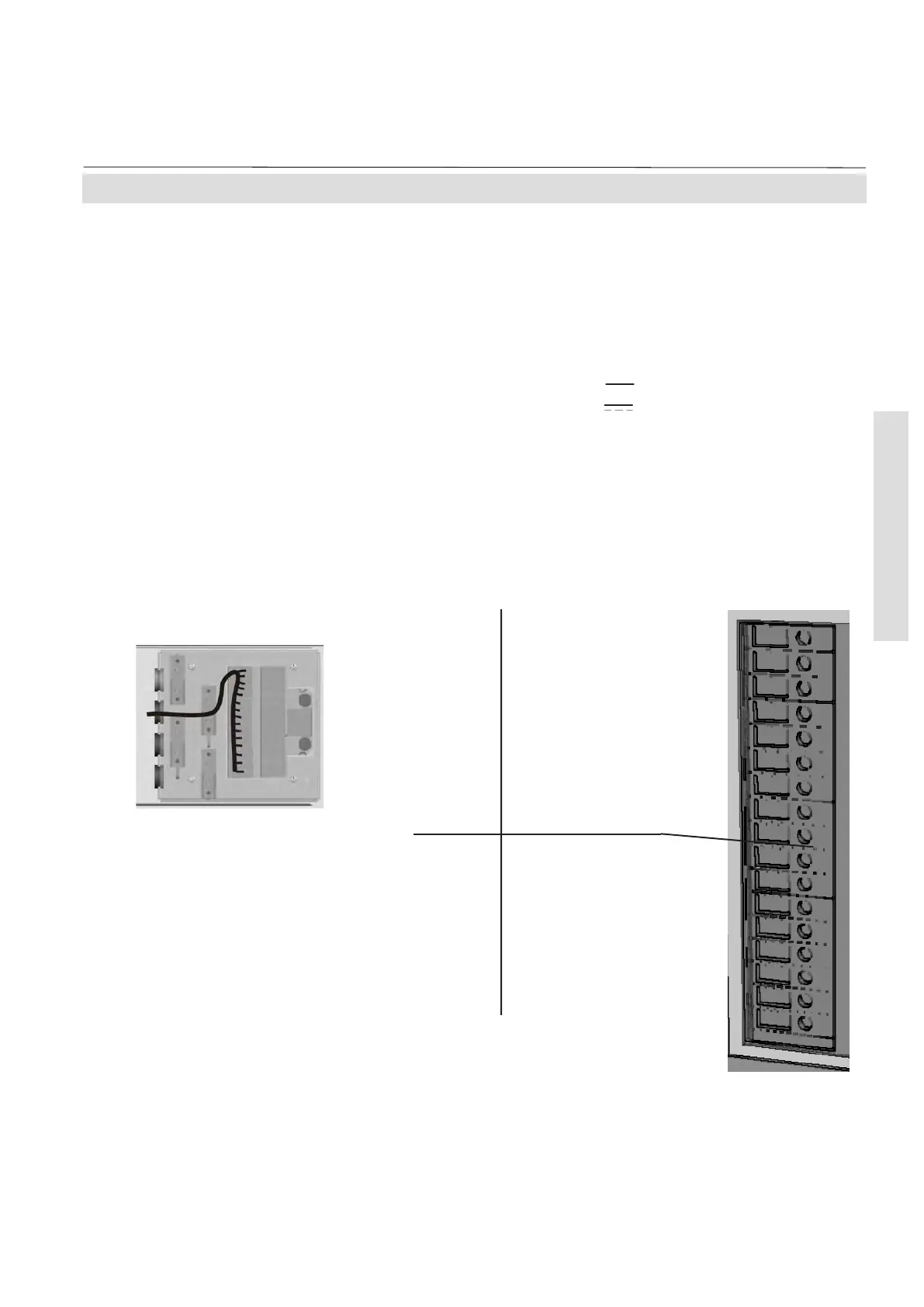
4-4-1 Installation - X-STREAM GP, X-STREAM GPS
Digital Inputs & Outputs
To connect the terminals remove the cover at
the analyzer's rear panel (4 screws). Feed the
digital I/O signal cable through the 2
nd
edge
protection, and through the 2
nd
strain-relief.
Fig. 4-15: Digital Input & Output Terminals
Design: Open collector (outputs)
Electrical specification:
outputs: max. 30 V , 30 mA
inputs: max. 30 V , internally limited to 2.3 mA
H level: min. 4 V; L level: max. 3 V
Note!
Take care of the special installation instructions
in section 3-5!
The leftmost terminals row is
reserved for the digital inputs
and outputs.
Terminal 1
Terminal 2
Terminal 3
Terminal 4
Terminal 5
Terminal 6
Terminal 7
Terminal 8
Terminal 9
Terminal 10
Terminal 11
Terminal 12
Terminal 13
Terminal 14
Terminal 15
Terminal 16
Terminal 17
Ch1: threshold 1
Ch1: threshold 2
Ch2: threshold 1
Ch2: threshold 2
Sample valve
Valve V4
Valve V1
Valve V2
DIG Out GND
Zero cal. Ch1 & Ch2
Span cal. Ch1
Span cal. Ch2
Open V4
Open V1
Open V2
Open sample valve or close all
DIG In GND
Digital Inputs DigitalOutputs
 Loading...


