Chapter 7: Automatic Exposure Control (AEC)
Definium 5000 X-Ray System 5197809-1EN Rev. 4 (13 February 2008) 7-4
Operator Manual © 2008 General Electric Company. All rights reserved.
Ion Chamber Detectors
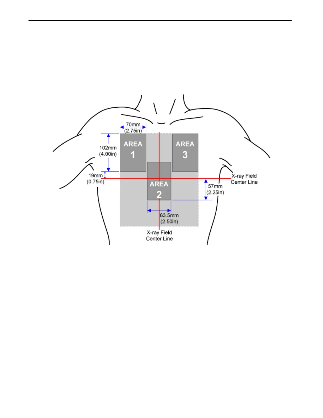
Ion Chamber Detectors have three sensing areas (Figure 7-3). Sensing Area 2 is located at the center of
the X-ray beam. While Area 1 and Area 3 can be selected to cover an exposure of two symmetrical parts
of the body, such as the lungs or the kidneys, care should be taken to center the patient and detector
areas accordingly.
Figure 7-3 Sensing areas
The position of the sensing areas are shown in relation to the area of a 210 mm x 248 mm (8.25in x
9.75in) Collimator Light Field.
Applications for Detector Sensing Areas
The detector sensing areas should be used as described in the following sections. You should become
familiar with their locations and recommended use. The sensing areas are numbered 1 through 3.
Areas 1 and 3
Areas 1 and 3 are used to cover symmetrical body parts. For example, acquiring a chest radiograph
includes the lungs, which are proportional parts of the body. In this application, Area 1 and 3 must be
located in line with radiation transmitted through the left and right lung fields. This ensures these areas
are not influenced by variations in tissue opacity caused by the heart or vertebrae.
FOR TRAINING PURPOSES ONLY!
NOTE: Once downloaded, this document is UNCONTROLLED, and therefore may not be the latest revision. Always confirm revision status against a validated source (ie CDL).
 Loading...


