398
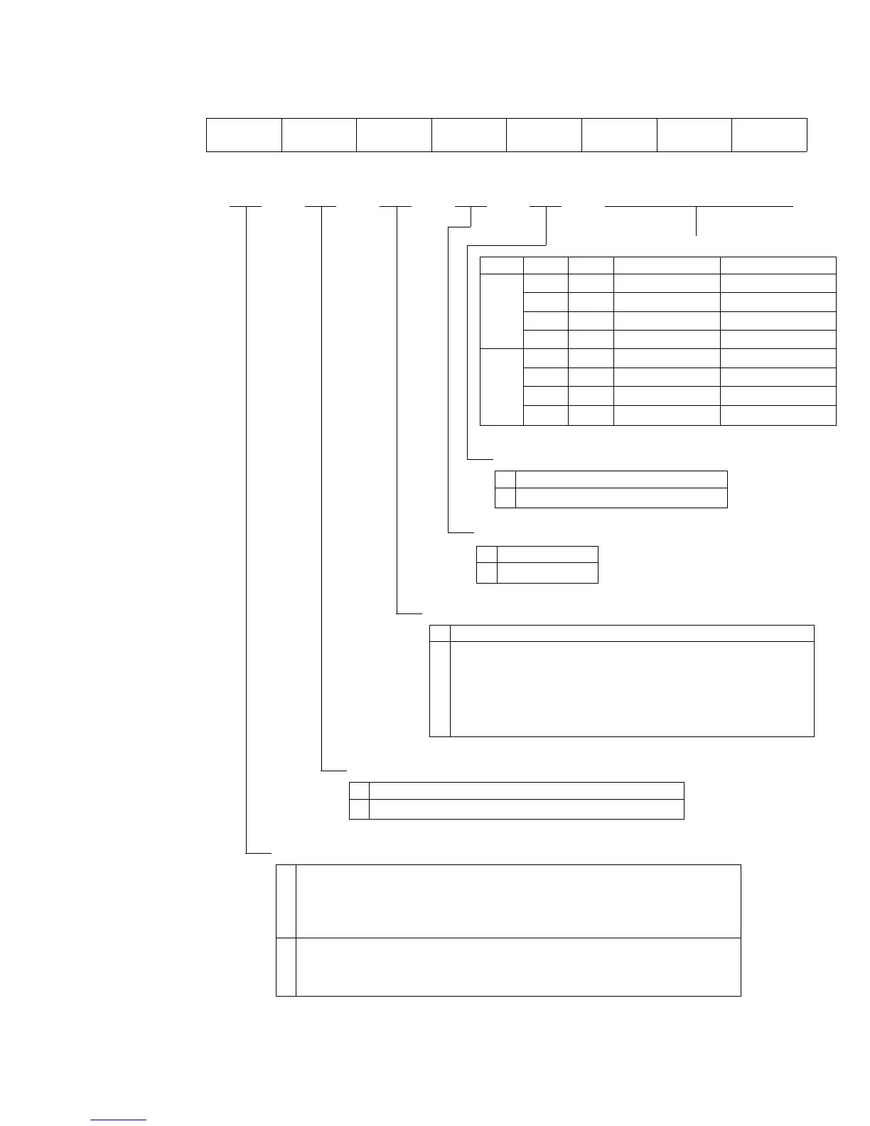
ADCSR—A/D Control/Status Register H'FFE8 A/D
Bit 76543210
ADF ADIE ADST SCAN CKS CH2 CH1 CH0
Initial value 00000000
Read/Write R/(W)* R/W R/W R/W R/W R/W R/W R/W
Channel Select
CH2 CH1 CH0 Single Mode Scan Mode
00 AN
0 AN0
01 AN1 AN0, AN1
10 AN2 AN0 to AN2
11 AN3 AN0 to AN3
00 AN4 AN4
01 AN5 AN4, AN5
10 AN6 AN4 to AN6
11 AN7 AN4 to AN7
0
1
Clock Select
0 Conversion time = 274 states
1 Conversion time = 138 states
Scan Mode
0 Single mode
1 Scan mode
A/D Start
0 A/D conversion is halted.
1 1. Single mode: One A/D conversion is performed,
then this bit is automatically cleared to 0.
2. Scan mode: A/D conversion starts and continues
cyclically on all selected channels until 0 is
written in this bit.
A/D Interrupt Enable
0 The A/D interrupt request (ADI) is disabled.
1 The A/D interrupt request (ADI) is enabled.
* Only writing of 0 to clear the flag is enabled.
A/D End Flag
0 Cleared from 1 to 0 when:
1. The chip is reset or enters a standby mode.
2. CPU reads ADF = 1, then writes 0 in ADF.
3. DTC is served by ADI.
1 Set to 1 at the following times:
1. Single mode: at the completion of A/D conversion.
2. Scan mode: when all selected channels have been converted.
Downloaded from Elcodis.com electronic components distributor

 Loading...
