COMMISSIONING
Part No.: 4417340 Revision 1 Service Manual 99
954 SmartServo FlexLine
In addition to the board’s [Health] LED LE1, the LEDs LE2 and LE3 are
available (see Figure 7-7). They can be associated to a relay, by setting
the [LED Association] entity.
☛
For a fail-safe level application, continue with section 7.3.6.10.
7.3.6.2 Operation Mode
The FII-DO can operate in one of two modes: [Alarm Mode] and
[Fallback Mode]. This is controlled by the [Operation Mode] entity.
Fallback Mode is not implemented yet.
☛
Set the [Operation Mode] entity to [Alarm Mode].
7.3.6.3 Relay Configuration
7.3.6.3.1 Jumper Settings
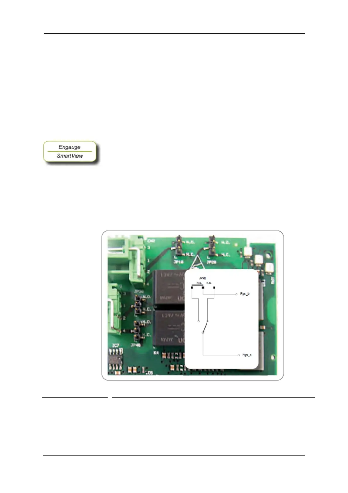
At installation, each individual relay contact was configured as required
with the hardware jumpers JPx0, where x = Relay 1 to 4 respectively.
See Figure 7-8.
Figure 7-8 The relays’ hardware jumpers
NOTE: In the Commissioning stage, no jumper setting can be changed
without breaking the compartment screw sealing.

 Loading...


