COMMISSIONING
158 Service Manual Part No.: 4417340 Revision 1
954 SmartServo FlexLine
7.3.9.7 Hardware Configuration
7.3.9.7.1 Jumper Allocation
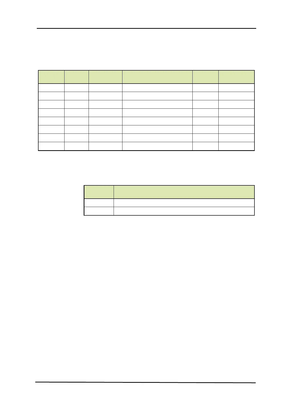
The following are typical jumper settings done on the HCI-HAO board.
Jumper
Number
Position
Connection
Details
Description
Default
Position
Default
Connections
JP1 ON Short 2 & 3 W&M Entity Protection OFF Short 1 & 2
JP2 ON Short 2 & 3 Password Read Protection OFF Short 1 & 2
JP3 ON Short 2 & 3 Write Protection All Entities OFF Short 1 & 2
JP4 ON Short 2 & 3 Free OFF Short 1 & 2
JP5 ON Short 2 & 3 Free OFF Short 1 & 2
JP6 ON Short 2 & 3 CAN termination 120E resistor OFF Short 1 & 2
JP7 & JP8 A Short 1 & 2 Active mode for Analog Output A Short 1 & 2
JP7 & JP8 P Short 2 & 3 Passive mode for Analog Output
7.3.9.7.2 LED Allocation
LED
Number
Function
LE2 HART data Transmit
LE3 HART data Receive

 Loading...


