MAINTENANCE
Part No.: 4417340 Revision 1 Service Manual 269
954 SmartServo FlexLine
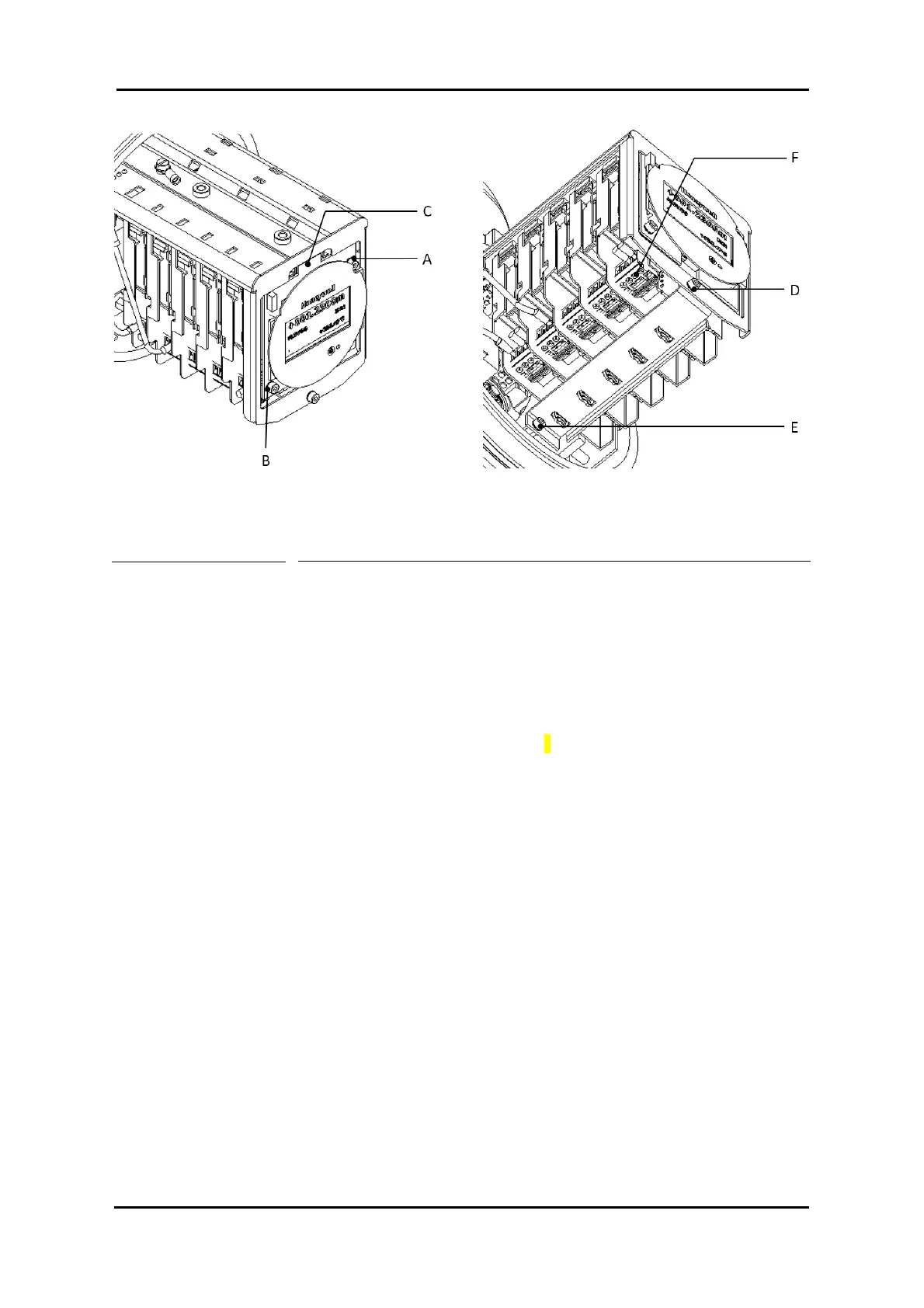
Figure 9-10 Position of CAN-LCD screws, clamping bracket, and FlexConn board connectors
To remove FlexConn boards, motor block and force tansducer proceed
as follows:
1. Identify how the wiring is routed in general and the positions of
option boards if there are any. This is helpful when replacing
the components or subassemblies.
2. Remove the clamping bracket by removing the two screws (D)
and (E) (refer to Figure 9-10).
3. Remove the connectors (F) of all FlexConn boards (refer to
Figure 9-10) and disconnect the grounding cables, if any, only
at the connector side. The other tip of the grounding cable will
stay fixed on the mounting bracket.
4. Remove all FlexConn boards by rotating them counter
clockwise direction using a proper tool on the engagement
point between black plastic cover and DIN-rail.
3. Remove the flat cable connecting the motor block to CAN-
SERVO.
4. Disconnect the force transducer cable.
5. Secure the motor frame with the transport bracket
6. Remove the two screws holding the force transducer by lifting it
slightly in order to release the span wire from the force
transducer.

 Loading...


