INS
GUI User’s Manual
Inertial Labs, Inc
TM
Address: 39959 Catoctin Ridge Street, Paeonian Springs, VA 20129 U.S.A.
Tel: +1 (703) 880-4222, Fax: +1 (703) 935-8377 Website: www.inertiallabs.com
161
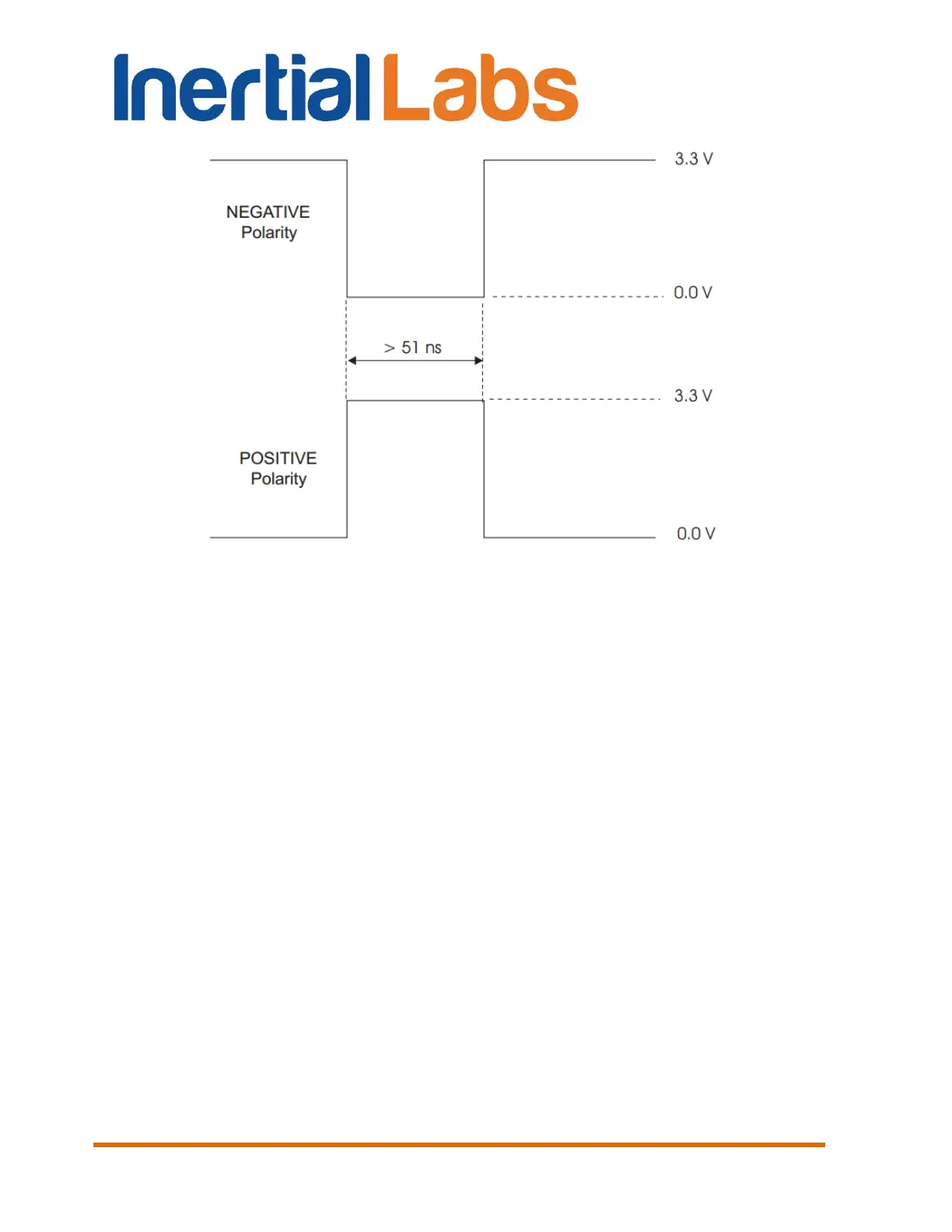
Fig. 13.1 PPS pulse
The leading edge of the PPS pulse is always the trigger / reference:
Negative – generates a normally high, active low pulse with the falling
edge as the reference;
Positive – generates a normally low, active high pulse with the rising
edge as the reference.
Since the INS firmware version 2.2.0.3 the PPS parameters are adjustable
and can be set using the Inertial Labs
TM
INS GUI since version 2.0.22.84
from 04/22/2016. For this go to “Options” menu, then to “Devices
Options”, “GNSS receiver” tab (see Fig. 4.4). It is possible there:
to enable or disable PPS output using check box. Default is PPS
enabled;
to change PPS polarity (negative or positive). Default is negative
polarity;
to change PPS period. Default is 1 second period;
to change PPS width. Default is 1000 microseconds.

 Loading...