INS
GUI User’s Manual
Inertial Labs, Inc
TM
Address: 39959 Catoctin Ridge Street, Paeonian Springs, VA 20129 U.S.A.
Tel: +1 (703) 880-4222, Fax: +1 (703) 935-8377 Website: www.inertiallabs.com
55
rev.2.10 and newer, section “6.16. Time stamps in INS messages” for more
details. Default setting is “Round time stamp” checked.
4.4. Swaying compensation
It is possible to increase the INS orientation accuracy at object swaying if to
compensate linear acceleration at place of the INS mounting. For this
purpose select “Swaying compensation options…” from the “Options”
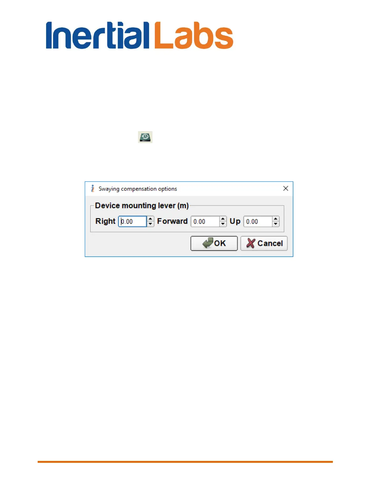
menu (Fig. 3.7) or click button (Fig. 3.1). A “Swaying compensation
options” dialog box (Fig. 4.26) will be opened that allow you to set the lever
of the INS mounting relative to the center of the object Swaying (usually this
is object center of gravity).
Fig. 4.26
The lever must be set in the carrier object axes – on the right, forward and
up. If after the INS mounting its axes X, Y, Z are parallel to the carrier object
lateral, longitudinal and vertical axes, then the INS position should be
measured in the directions of the INS X, Y and Z axes. If the INS unit is
mounted on the object in othe known position (up to upside-down, upright
etc., see Appendix E. Variants of the Inertial Labs
TM
INS mounting relative to
the object axes), then set the INS position just in the object axes (on the
right, forward and up directions), but not in the INS axes.

 Loading...