INS
GUI User’s Manual
Inertial Labs, Inc
TM
Address: 39959 Catoctin Ridge Street, Paeonian Springs, VA 20129 U.S.A.
Tel: +1 (703) 880-4222, Fax: +1 (703) 935-8377 Website: www.inertiallabs.com
248
APPENDIX H.
Using Ethernet port for communication with the
Inertial LabsTM INS
This Appendix describes the basics of communication with the INS unit
which have built-in Ethernet port. Such INS unit is equipped with USR-
TCP232-ED2 module made by USR-IOT. This document refers to the
website of USR-IOT as to the location of required software tools and
datasheets, http://www.usriot.com/p/modbus-tcp-ethernet-ip-modules/
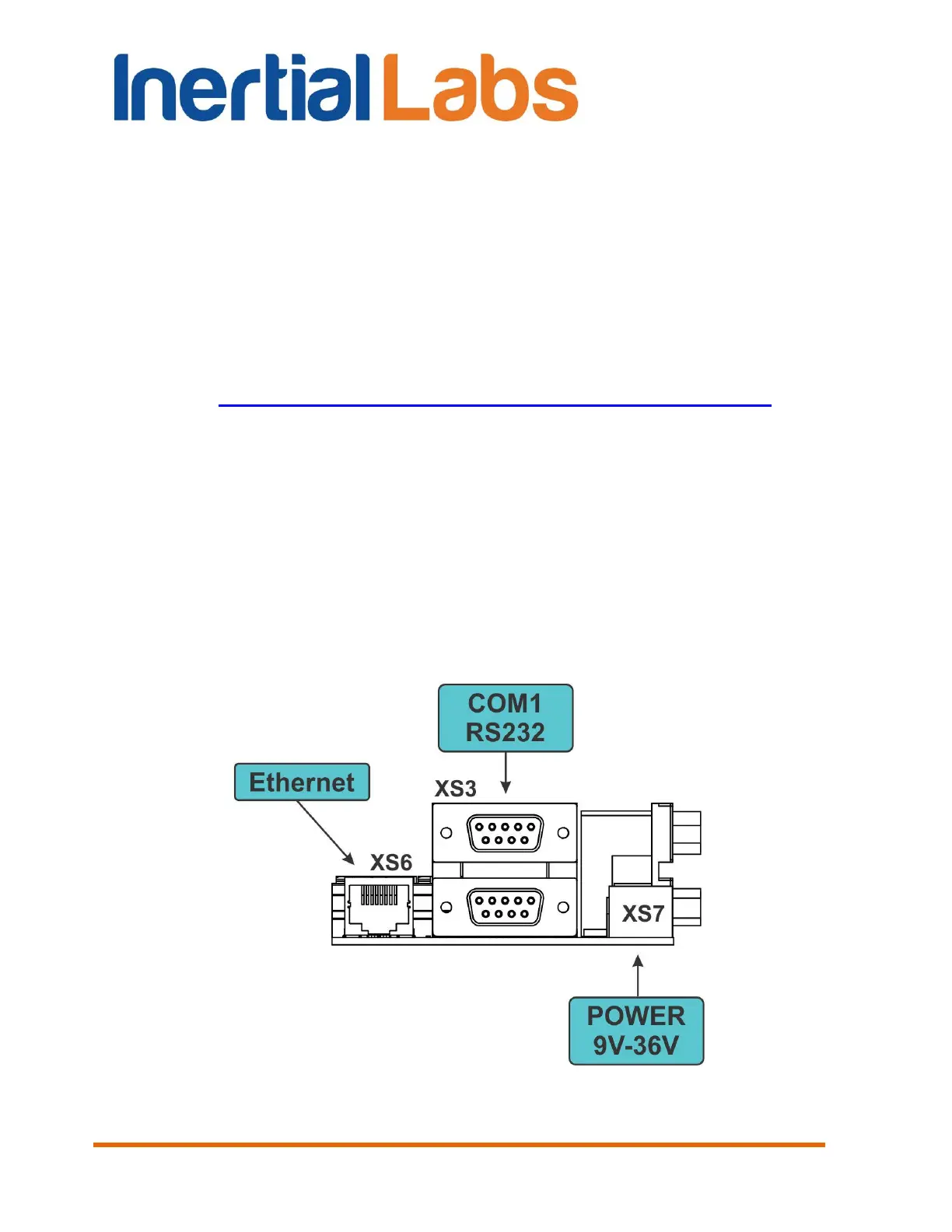
H.1. Connection overview
The Inertial Labs
TM
INS is delivered to a customer with the multi-conductor
cable. One side of the cable should be connected to the connector on the
rear wall of the device. The other side of the cable is attached to the
breakout board with numerous connectors on it (see Fig. H.1). The
connectors needed for Ethernet communication are XS6 (used for a data)
and XS7 (used for a power). The INS with Ethernet retains the
communication via a serial port as well. So XS3 can also be used as RS232
port if necessary.
Fig. H.1

 Loading...