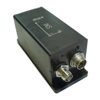
INS
GUI User’s Manual
Inertial Labs, Inc
TM
Address: 39959 Catoctin Ridge Street, Paeonian Springs, VA 20129 U.S.A.
Tel: +1 (703) 880-4222, Fax: +1 (703) 935-8377 Website: www.inertiallabs.com
101
Also you can plot saved INS binary data using “File” menu. See section 6.1
for more details.
10.2. Control of the GNSS receiver
The Inertial Labs
TM
INS has onboard high-grade Global Navigation Satellite
System (GNSS) receiver which provide high accurate position using the next
GNSS systems:
GPS L1, L2, L2C;
GLONASS L1, L2;
Galileo E1;
BeiDou B1;
Compass3;
SBAS;
QZSS.
The base model of the onboard receiver is G1S00G0T0 and has the next
possibilities: GPS L1 code position, DGPS, SBAS, measurement data rate
20 Hz, no raw data output. See section “10.2.2. Control of GNSS receiver
model” for description of procedure of changing the receiver model to get
more features from the GNSS receiver.
See sections “13.1. Control of PPS output signal” and “13.2. Processing of
mark input signal” for adjustment of synchro output and input signals for the
GNSS receiver.
10.2.1. GNSS correction
The Inertial Labs
TM
INS has three COM-ports. COM3 port can be used to
receive data for differential corrections of GNSS.
GNSS corrections are used to improve position accuracy of the INS. There
are two types of GNSS corrections: correction data from Satellite Based
Augmentation Systems (SBAS) and Differential GPS (DGPS) correction
data transmitted from a base station. For using GNSS correction open the
“GNSS receiver” tab in the “Device options” menu (Fig. 4.4), and follow the
next steps to set GNSS correction:

 Loading...