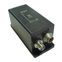
INS
GUI User’s Manual
Inertial Labs, Inc
TM
Address: 39959 Catoctin Ridge Street, Paeonian Springs, VA 20129 U.S.A.
Tel: +1 (703) 880-4222, Fax: +1 (703) 935-8377 Website: www.inertiallabs.com
39
4.2.4.1. Parameters of encoder-based odometer
INS GUI supports INS operation with two types of odometers:
odometer with OBDII interface (converted to RS-232);
encoder-based odometer (wheel speed sensor) with pulse/bi-phase
signals.
Parameters of OBDII odometer connection to INS COM4 port can be set in
“CAN / COM4” tab of the “Devices options…” window (see section 4.2.5).
Note INS unit should be equipped to accept encoder-based odometer data.
Please contact Inertial Labs for information about this.
For using encoder-based odometer it is necessary to check “Encoder-
based odometer” checkbox (see Fig. 4.13) and configure the next
parameters:
– Pulse length is the distance in meters between low to high transitions of
the encoder signal;
– Odometer offset is the lever arm measured from the accelerometer
mass-center of the INS unit to the point at which the vehicle's tire makes
contact with the road in the vehicle co-ordinate frame, in the right,
forward and vertical directions.
– STD_Vh (m/s) is standard deviation of the odometer noise. Usually its
value is 0.10 m/s, but it depends on encoder.
– k_Sigma_V is residual threshold. Its default value is 10.
Please contact Inertial Labs to get recommendations for odometer
parameters value.
See section “10.7. INS operation with odometer” for more details.
4.2.4.2. Using the main COM1 port to receive external aiding data
The Inertial Labs
TM
INS uses the main COM1 port for commands and data
transfer between the Inertial Labs
TM
INS and the host computer.
Since INS firmware version 2.8.2.0 it is possible to send external aiding data
to INS unit using the main COM1 port during INS ordinary operation when
INS outputs data through COM1 port.

 Loading...