INS
GUI User’s Manual
Inertial Labs, Inc
TM
Address: 39959 Catoctin Ridge Street, Paeonian Springs, VA 20129 U.S.A.
Tel: +1 (703) 880-4222, Fax: +1 (703) 935-8377 Website: www.inertiallabs.com
187
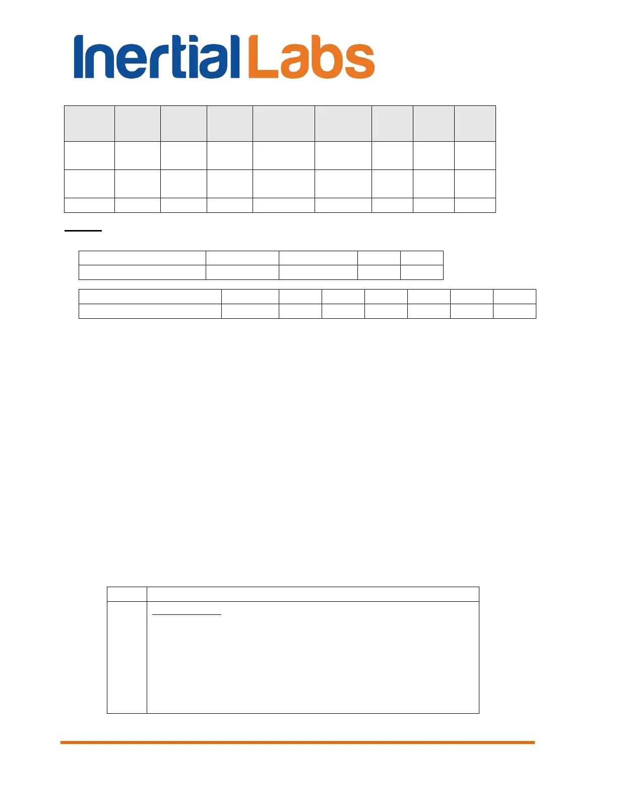
Table C.3 (continued)
Notes:
1. Values of KG, KA are scale factors depending on gyro and accelerometer range:
2. Angular rates, linear accelerations and magnetic fields are in the carrier object axes (X
is lateral axis, Y is longitudinal axis, Z is vertical axis). The INS orientation relative to the
carrier object axes is set by alignment angles (see Appendix E. Variants of the Inertial
Labs
TM
INS mounting relative to the object axes).
3. g = 9.8106 m/s
2
.
4. USW is unit status word (see Appendix D for details).
5. Vinp is input voltage of the INS.
6. Temper is averaged temperature in 3 gyros.
7. ms_gps are milliseconds from the beginning of the GPS reference week;
8. GNSS_info1, GNSS_info2 contain information about GNSS data (see Table C.4,
Table C.5);
9. #SolnSVs is number of satellites used in navigation solution;
10. V_latency is latency in the velocity time tag in milliseconds;
11. P_bar, H_bar – pressure and barometric height.
12. New_GPS is indicator of new update of GPS data (see Table C.6);
13. The low byte is transmitted by first.
Table C.4 GNSS_info1 – information about GNSS data
Position type:
0 – Single point position;
1 – DGPS (pseudorange differential solution);
2 – Solution calculated using corrections from SBAS;
3 – PPP solution;
4 – RTK (other) solution;
5 – RTK (narrow-int) solution;
6 – Other.

 Loading...