INS
GUI User’s Manual
Inertial Labs, Inc
TM
Address: 39959 Catoctin Ridge Street, Paeonian Springs, VA 20129 U.S.A.
Tel: +1 (703) 880-4222, Fax: +1 (703) 935-8377 Website: www.inertiallabs.com
241
APPENDIX F.
Installation of the GNSS antennas
F.1. Installation of single GNSS antenna
Usually the INS unit and GNSS antenna are installed in different places of
the carrier object. Moreover, placement of the antenna close to the INS unit
is undesirable because of the antenna impact on the INS magnetometers.
While the best place for the INS unit is center of gravity of the carrier object,
the GNSS antenna must of course be placed with a clear view of the sky
with a sufficient ground plane.
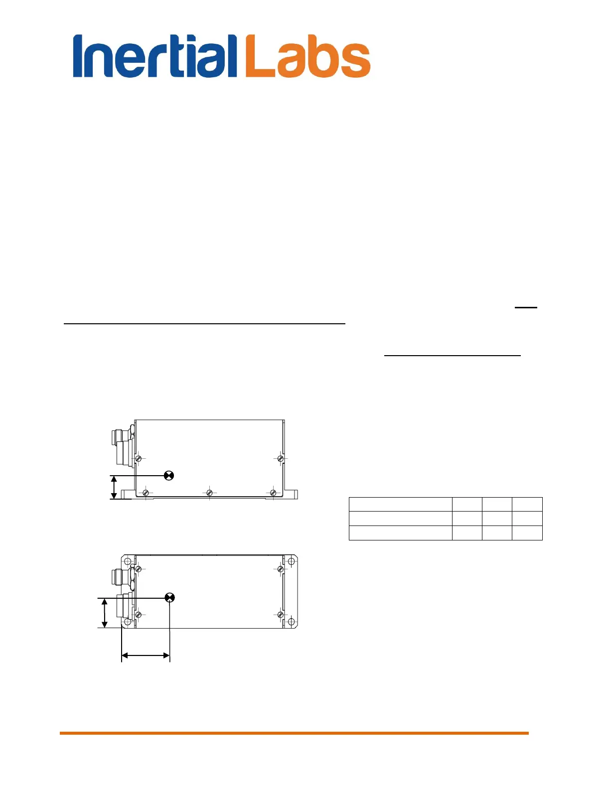
After the INS unit and GNSS antenna installation on the carrier object it is
necessary to measure the antenna position relative to the accelerometer
mass-center of the INS unit (see Fig. F.1, Fig. F.2), in the object axes – on
the right, forward and up. Then it is necessary to set these coordinates in
appropriate fields in the IMU tab (see section 4.2.1) and store them in the
INS nonvolatile memory.
Fig. F.1 Position of the accelerometer mass-center in in housed Inertial Labs
TM
INS
unit

 Loading...