INS
GUI User’s Manual
Inertial Labs, Inc
TM
Address: 39959 Catoctin Ridge Street, Paeonian Springs, VA 20129 U.S.A.
Tel: +1 (703) 880-4222, Fax: +1 (703) 935-8377 Website: www.inertiallabs.com
242
Note: Variant 1 includes INS-P, INS-B units with serial numbers up to F1710189 and
INS-D units with serial numbers up to F1691036; Variant 2 includes all other INS units.
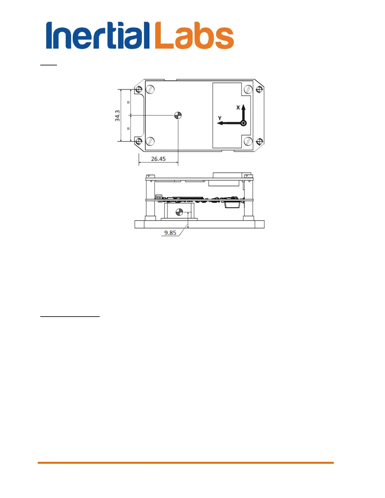
Fig. F.2 Position of the accelerometer mass-center in Inertial Labs
TM
INS-OEM unit
(in millimetres)
Fig. F.3 shows positive right, forward and up directions of the antenna
position relative to the INS unit.
Important notes:
1. If after the INS mounting its axes (see Fig. E.1) are parallel to the carrier object axes,
then the antenna coordinates should be measured in the directions of X, Y and Z axes.
2. On the other hand, the INS unit can be mounted on the object in any known position
(up to upside-down, upright etc., see Appendix E. Variants of the Inertial Labs
TM
INS
mounting relative to the object axes). In that case please set the GNSS antenna
coordinates measures just in the object axes (on the right, forward and up directions), but
not in the INS axes.

 Loading...