INS
GUI User’s Manual
Inertial Labs, Inc
TM
Address: 39959 Catoctin Ridge Street, Paeonian Springs, VA 20129 U.S.A.
Tel: +1 (703) 880-4222, Fax: +1 (703) 935-8377 Website: www.inertiallabs.com
236
APPENDIX D.
The Unit Status Word definition
The Unit Status Word (USW) provides the INS state information. The low
byte (bits 0-7) of USW indicates failure of the INS. If this byte is 0, the INS
operates correctly, if it is not 0, see the Table D.1 for type of failure. The high
byte (bits 8-15) contains a warning or is informative for the user. Status of
each bit of the USW warning byte is specified in the Table D.1.
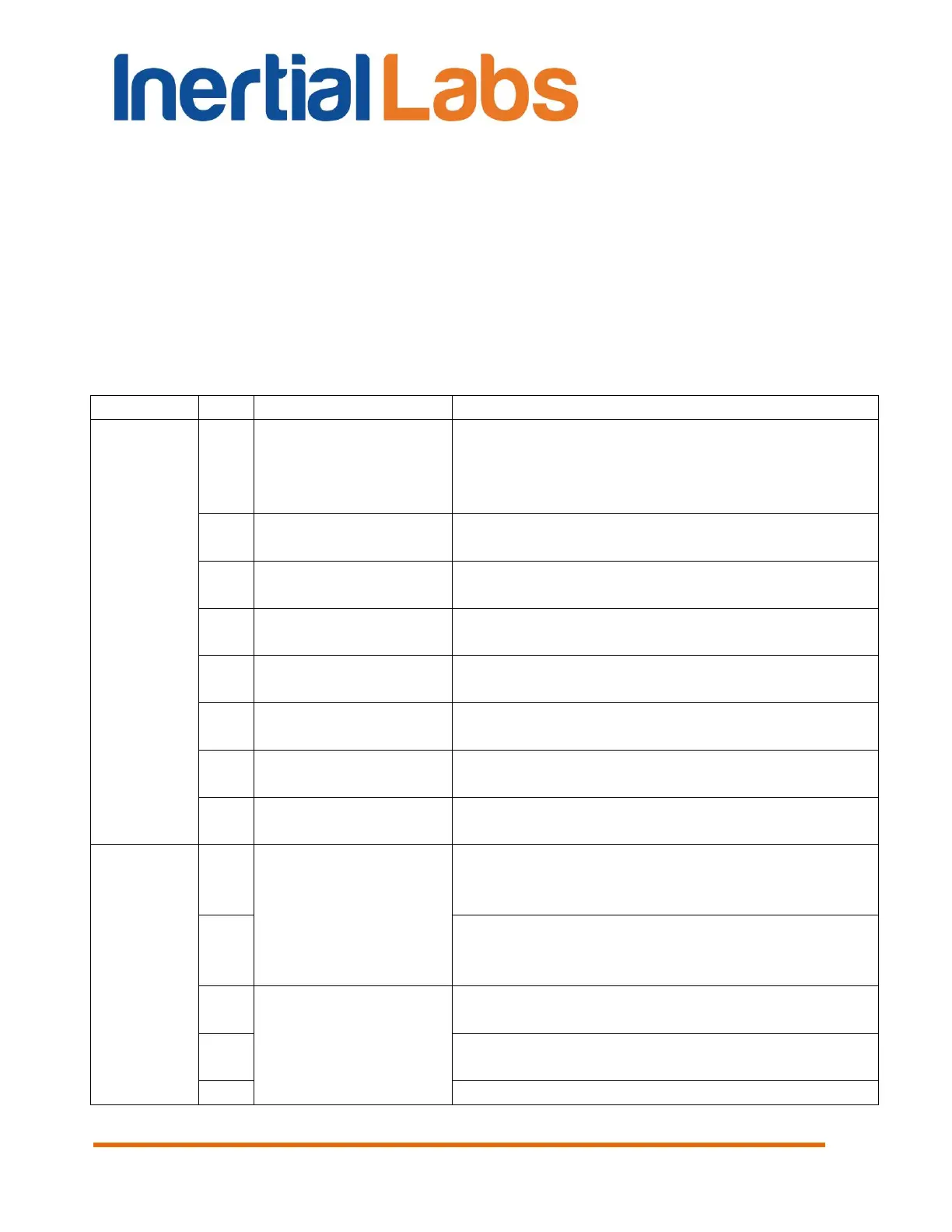
Table D.1 The Unit Status Word description
0 – Successful initial alignment
1 – Unsuccessful initial alignment due to INS
moving or large change of outer magnetic
field
0 – Parameters are correct
1 – Parameters are incorrect
0 – No failure
1 – Failure is detected
0 – No failure
1 – Failure is detected
0 – No failure
1 – Failure is detected
0 – No failure
1 – Failure is detected
0 – No failure
1 – Failure is detected
1 – during data accumulation and calculation
0 -- otherwise
0 – Supply voltage is not less than minimum
level
1 – Low supply voltage is detected
0 – Supply voltage is not higher than
maximum level
1 – High supply voltage is detected
Angular Rate
Exceeding Detect
0 – X-angular rate is within the range
1 – X-angular rate is outrange
0 – Y-angular rate is within the range
1 – Y-angular rate is outrange
0 – Z-angular rate is within the range

 Loading...