INS
GUI User’s Manual
Inertial Labs, Inc
TM
Address: 39959 Catoctin Ridge Street, Paeonian Springs, VA 20129 U.S.A.
Tel: +1 (703) 880-4222, Fax: +1 (703) 935-8377 Website: www.inertiallabs.com
238
APPENDIX E.
Variants of the Inertial LabsTM INS mounting relative
to object axes
The Inertial Labs
TM
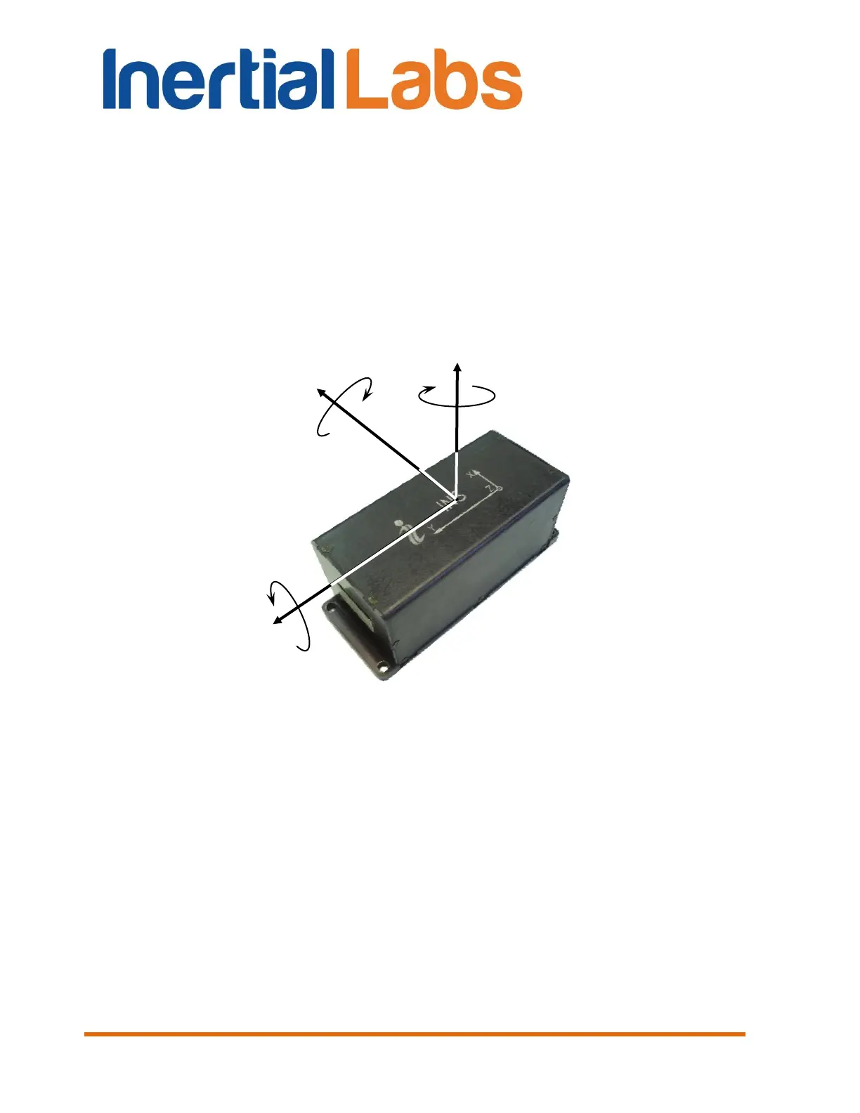
INS has axes orientation shown on Fig. E.1. At usual
installation of the INS on carrier object the INS X, Y, Z axes should be
parallel to the object lateral, longitudinal and vertical axes.
Fig. E.1 Coordinate system of the Inertial Labs
TM
INS
But the Inertial Labs
TM
INS can be mounted on the object in any known
position (up to upside-down, upright etc.) relative to the object axes. Such
mounting doesn’t change right calculation of the object orientation if angles
of the INS mounting are correctly stored in the INS nonvolatile memory.
To set these angles select item “Device option …” from the “Options” menu.
In opened window Fig. 4.2 angles of the INS mounting are in the “Alignment
angles” section.
The INS alignment angles are set in the next order (like azimuth, pitch and
roll setting):

 Loading...