INS
GUI User’s Manual
Inertial Labs, Inc
TM
Address: 39959 Catoctin Ridge Street, Paeonian Springs, VA 20129 U.S.A.
Tel: +1 (703) 880-4222, Fax: +1 (703) 935-8377 Website: www.inertiallabs.com
244
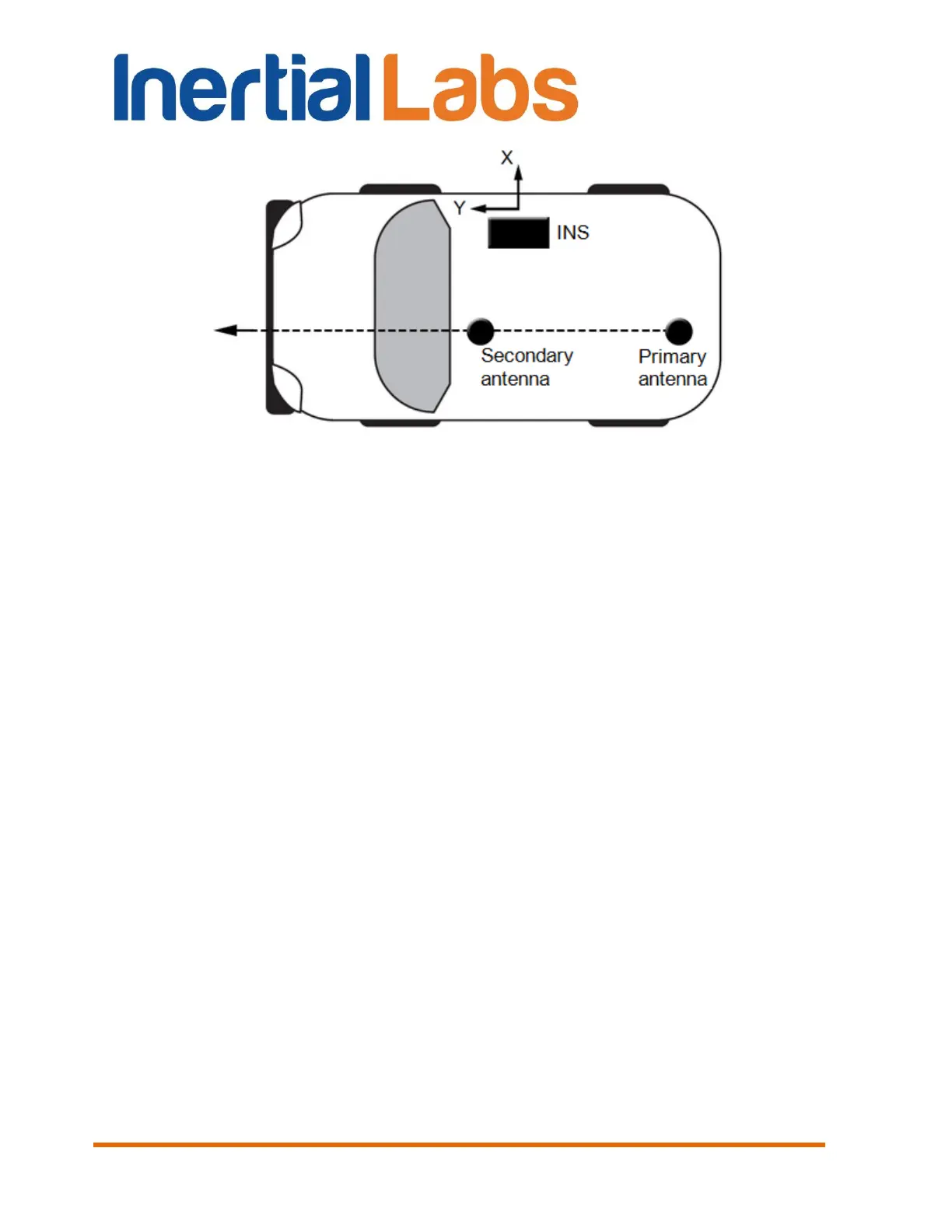
Fig. F.4 Installation of the primary and secondary GNSS antennas on carrier object
Since the firmware version 2.9.1.7 the INS-D algorithm has the feature of the
secondary antenna installation in arbitrary (but known) position relative to
the INS-D unit and the primary antenna. It is possible to set secondary
antenna location in two ways: by specifying its position in meters relative to
the accelerometer mass-center of the IMU in the ‘Secondary antenna
position relative to the IMU (m)’ fields or by specifying the antennas baseline
orientation in degrees in the ‘Antennas baseline orientation (deg)’ fields (see
Fig. 4.2 in section 4.2.1).
Fig. F.5 shows Alpha and Beta angles of the antennas baseline orientation
relative to the INS unit. Alpha angle is measured in horizon plane of the
object, clockwise direction is positive. Beta angle is measured in vertical
plane, positive is up. Note that on the Fig. F.5 there are positive Alpha and
negative Beta angles.

 Loading...