2 - 4
PN 074-550-P1D
SQC-310 Operating Manual
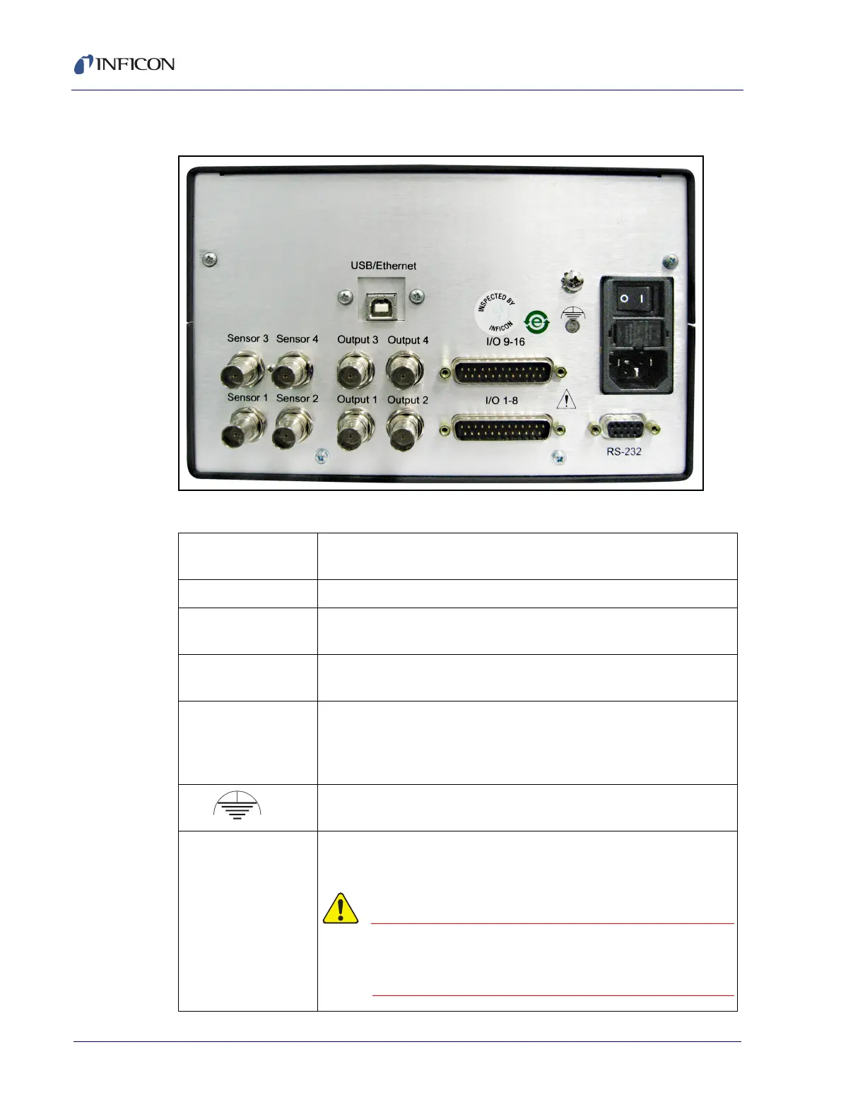
2.3 Rear Panel
Figure 2-2 Rear panel
Table 2-3 Rear panel connections
Sensor 1 and 2 BNC connection to the oscillators for sensor 1 and 2 (see section
2.4 on page 2-5).
Output 1 and 2 BNC connection to the source power supply control voltage input.
I/O 1-8 25 Pin D-sub connection for 8 relays (outputs) and 8 digital inputs.
For use with external equipment (see section 2.8 on page 2-11).
RS-232
USB or Ethernet
Connection to a computer for programming and data acquisition.
RS-232 and USB are standard. Ethernet option replaces USB.
Sensor 3 and 4
Output 3 and 4
I/O 9-16
These Sensor, Output, and I/O Ports are optional with SQC-310
and standard with SQC-310C.
Ground terminal for common system and cable grounding.
Power Input and
Fuse
Connects to mains power. SQC-310 automatically detects mains
voltages of 100 to 120 and 200 to 240 V (ac), 50/60 Hz.
Only use a power cable and fuse of the
specified rating (refer to section 1.4.5,
Power, on page 1-7).