2 - 11
PN 074-550-P1D
SQC-310 Operating Manual
2.7.2.2 Installation
1 Align the two controllers side by side, as though installed in the rack. Remove
the two adjacent screws on the rear panel of each SQC-310.
NOTE: These screws are no longer needed and may be discarded.
2 Install the rear mount couplers. Using the 4 pan head screws and washers
provided, install one side of the rear mount coupler to each SQC-310. Do not
fully tighten the screws until all screws are installed.
3 Install the rack mount ears. Using the 4 flat head screws provided, install the
rack mount ears on the outer ends of the controller assembly. One rack mount
ear should be installed on each SQC-310.
4 Mount the SQC-310 assembly. Slide the assembly into an empty 2U
rack-mount space (8.9 cm [3.5 in.] H x48.3 cm [19 in.] W). Secure the assembly
with four rack screws (not provided).
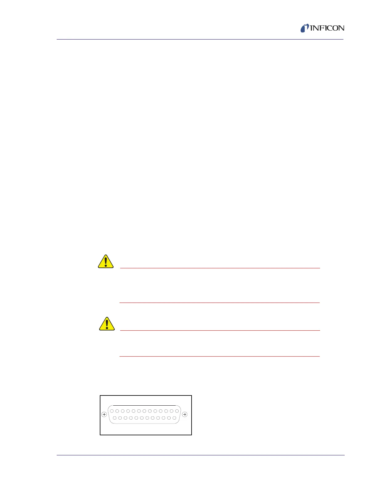
2.8 I/O Connections
A 25-pin, D-sub connector, located on the SQC-310 rear panel, provides
Input/Output connections.
Inputs can be activated by connecting to a switch and shorting to ground,
or they can be driven by a TTL compatible signal.
These are not isolated inputs. The voltage level applied
must be limited to between 0 and +5 V with respect
to ground.
Output relays are rated for 30 V (rms) or 30 V (dc), 2 A
maximum.
The pin assignments for the rear panel mounted I/O connector are displayed
in Figure 2-9 and Table 2-5
Figure 2-9 Rear panel I/O pin assignments