5 - 16
PN 074-550-P1D
SQC-310 Operating Manual
Used By. . . . . . . . . . . . . . . . . . . . . . Indicates if an input function is defined by a
sensor, source, or logic statement. Since
multiple logic statements may use an input in
the IF condition, only the first use is listed.
Function is automatically designated by
SQC-310 and cannot be edited.
When either the Show Relays or Show Inputs button is clicked, the View Status
may be selected. View Status monitors the state of the SQC-310 inputs and relays.
Similar to the SQC-310 display, relays and inputs whose state is currently true are
displayed in green. False is displayed in red.
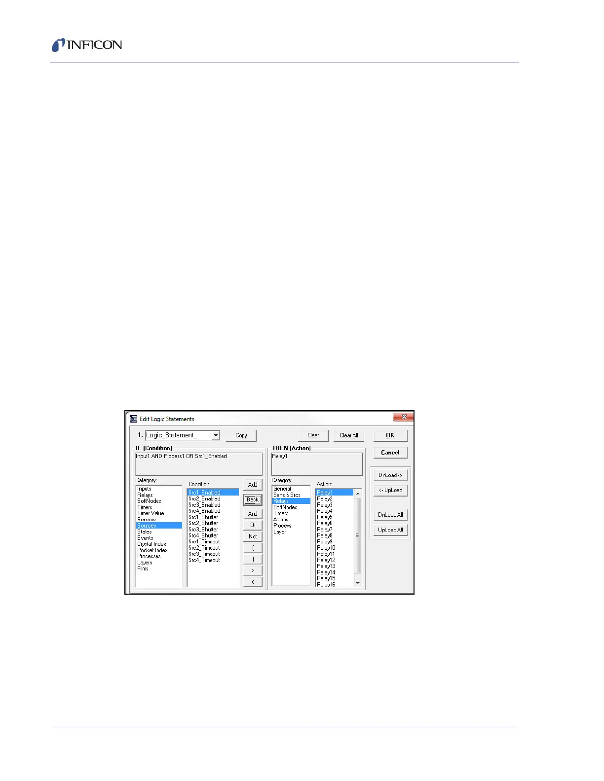
5.5.7 Logic Statements Menu
In the Instrument window toolbar, click Edit >> Logic... to display the Logic
Statements menu. Logic statements allow the programming of SQC-310 to
respond to inputs and activate relays, based on a variety of process conditions (see
Figure 5-12).
NOTE: Logic statements are closely linked to digital I/O definitions. Changing a
statement may cause SQC-310 to alter internal I/O definitions. SQC-310
must be connected and any changes made must be downloaded to verify
and modify the SQC-310 configuration before OK can be selected to close
the Logic Statements menu and save the data to memory.
Figure 5-12 Logic Statements menu