Chapter 3: Operating Principles
The Nova Touch-Screen
Eclipse User Guide 2.0 73/ 526
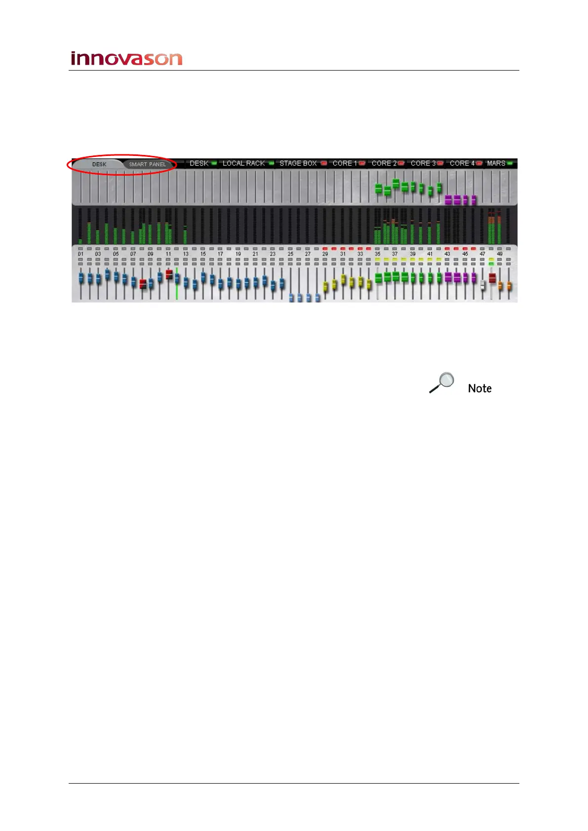
The DESK/SMART PANEL Overview
The lower half of the Main Mix display provides a visual
overview of your mix. It can be switched to show the DESK
(Fader strips 1 to 48) or SMART PANEL (controllers 1 to 48):
To help identify different channel types, each fader is colour
coded. Blue faders are mono inputs and red/black faders are
stereo inputs. The remaining colours follow the ID colours, see
Page 58.
Note that the selected channel is shown with a green fader
track – in our example, input Fader 12 is the selected channel.
Working from top to bottom, the display shows:
• Send levels – the upper row of faders shows the level
of Aux (green) or Matrix (violet) sends from the selected
channel.
• VU metering – identical to the VU meters on the
console surface. If a channel is stereo, then the screen
VUs meter both left and right components.
• MUTE status – any red buttons indicate that a channel is
muted. For example, faders 29 to 34 are muted.
• Fader number – 1 to 48 for visual reference only.
Faders 49 and 50 represent the monitor output level set
on the TB/MONITORING panel.
• Bus Routing – any yellow buttons indicate bus
assignments from the selected channel. In our example,
the selected input fader is routed to Auxes controlled
from faders 35 to 42.
• CUE status - any green buttons indicate that a channel
CUE is active.
• Main levels – the lower row of faders shows the main
level of each channel. Note that stereo faders are wider
than mono faders, so in our example we can see that
the first four Auxes are stereo.
Note that the display changes as you change the selected
channel to provide forward or reverse interrogation of routing
and send levels.