Chapter 6: Console Configuration
The Patch Input Display
Eclipse User Guide 2.0 231/ 526
The Patch Input Display
1. Select the PATCH INPUT display by pressing the
PATCH IN button on the UTILITIES panel.
2. And make sure that the PATCH and DIO1 tabs are
selected:
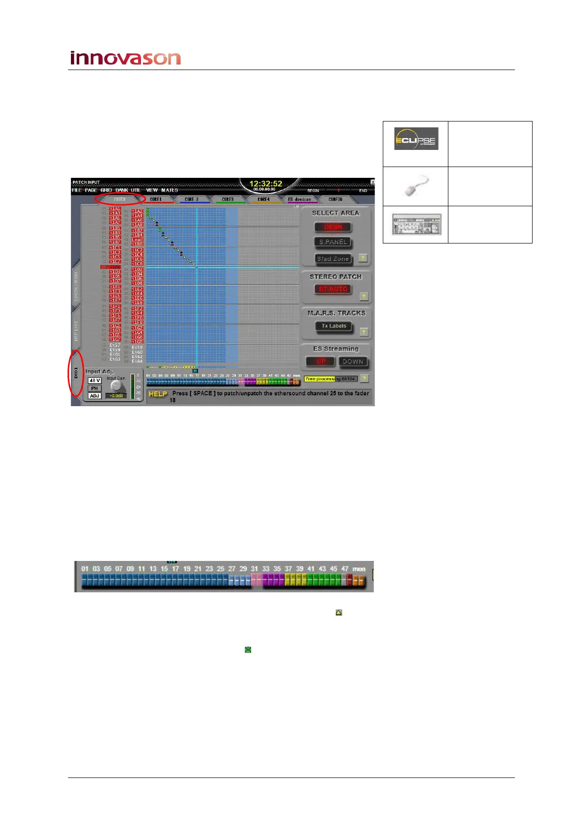
This grid is used to patch Ethersound channels (on the left) to
input faders (at the bottom).
The Ethersound channels are colour coded to show their origin:
red for sources from DioCore 1, blue for sources from DioCore
2, and so on. If the Ethersound channel has no source, then it is
white. The colour coding follows the CORE and ES devices tab
colours at the top of the display. See Page 263 for more details
on preparing the Ethersound network.
At the bottom of the display, the colour coding of the faders
shows their channel type (inputs, VCAs, Auxes, etc.):
Mono connections are indicated by a yellow triangle within
the grid. Stereo connections are indicated by black and red
triangles for left and right. Connections made to a Smart Fader
VCA are indicated with green boxes .
Note that some parts of the grid are light (patching allowed) and
others are dark (patching not allowed). This is because the
PATCH INPUT grid is only used to connect sources to input
channels. Therefore, if a fader is assigned to a mix bus or a
VCA, there is no input patch available.
Patch IN
(UTILITIES)
“GRID ->
Patch Input”
[F11]