Model 2651A High Power System SourceMeter® Instrument Reference Manual Section 3: Functions and features
2651A-901-01 Rev. A / March 2011 3-85
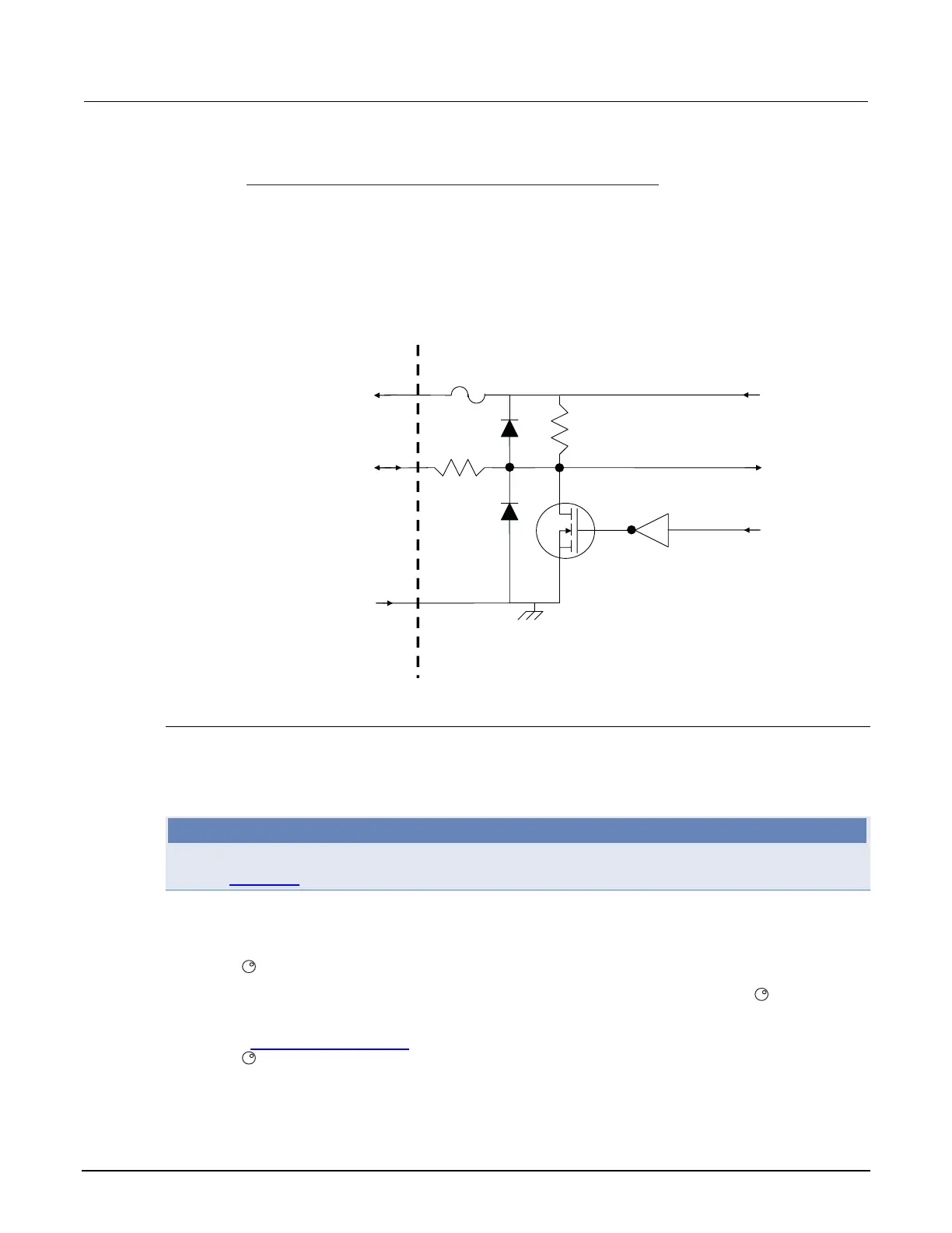
Figure 68: Digital I/O port configuration
+5 VD
5.1 kΩ
100 Ω
DIGITAL I/O INTERFACE:
Connector: 25-pin female D
Input/Output pins: 14 open-drain I/O bits
Absolute maximum input voltage: 5.25 V
Absolute minimum input voltage: -0.25 V
Maximum logic low input voltage: 0.7 V @ +850 μA
Minimum logic high input voltage: 2.1 V @ +570 μA
Maximum source current (flowing out of digital I/O bit): +960 μA
Absolute Maximum sink current (flowing into digital I/O bit): -11.0 A
Maximum Sink Current @ Maximum Logic Low Voltage (0.7 V): -5.0 mA.
+5 V pin
(on DIGITAL I/O connector)
Solid state
fuse
DIGITAL I/O pin
(on DIGITAL I/O connector)
Read by firmware
Rear panel
Written by firmware
GND pin
(on DIGITAL I/O connector)
Controlling digital I/O lines
Although the digital I/O lines are primarily intended for use with a device handler for limit testing, they
can also be used for other purposes such as controlling external logic circuits. You can control lines
either from the front panel or over a remote interface.
NOTE
The trigger mode for the line must be set to digio.TRIG_BYPASS in order to use the line for digital
I/O. See Triggering (on page 3-32) for more information.
To set digital I/O values from the front panel:
1. Press the MENU key, select DIGOUT, and then press the ENTER key or press the navigation
wheel
.
2. Select DIG-IO-OUTPUT, and then press the ENTER key or the navigation wheel
.
3. Set the decimal value as required to set digital I/O lines within the range of 0 to 16,383 (see the
table in Digital I/O bit weighting
(on page 3-87)), and then press the ENTER key or the navigation
wheel
.
4. Press the EXIT (LOCAL) key as needed to return to the main menu.

 Loading...


