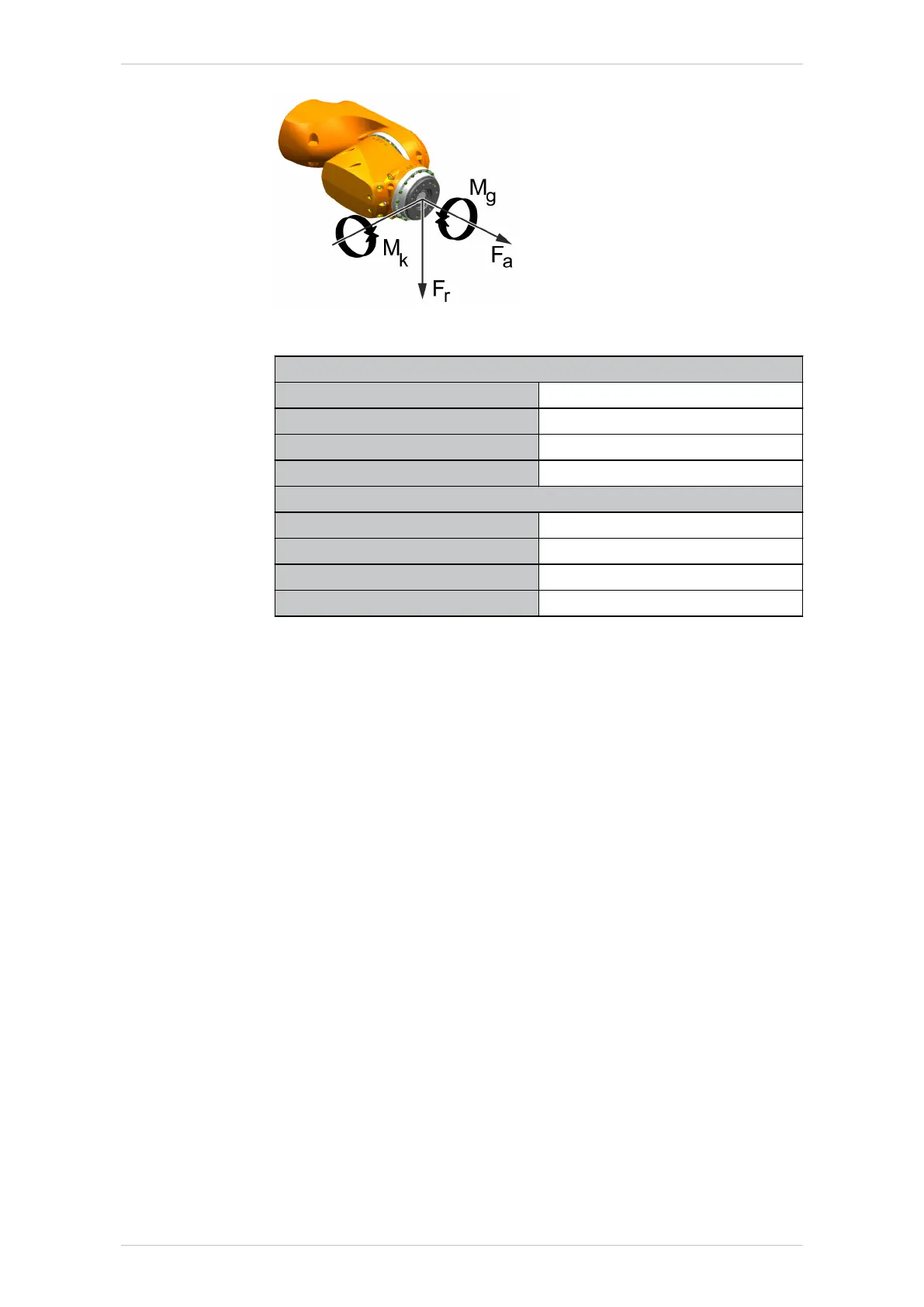
Fig. 4-74: Flange loads
Flange loads during operation
F(a) 1924 N
F(r) 2015 N
M(k) 557 Nm
M(g) 401 Nm
Flange loads in the case of EMERGENCY STOP
F(a) 2241 N
F(r) 3882 N
M(k) 1263 Nm
M(g) 871 Nm
Axial force F(a), radial force F(r), tilting torque M(k), torque about mount-
ing flange M(g)
Supplementary load
The robot can carry supplementary loads. The fastening holes on the arm,
link arm and rotating column are used, for example, for fastening the cov-
ers or external energy supply systems. The fastening holes on the in-line
wrist are exclusively for fastening holders for energy supply systems (e.g.
holders for compressed air hose).
When mounting the supplementary loads, be careful to observe the maxi-
mum permissible total load. The dimensions and positions of the installa-
tion options can be seen in the following diagrams.
KR IONTEC
122/344 | www.kuka.com MA KR IONTEC V4 | Issued: 11.05.2021
Technical data

 Loading...

