is connected via ring cable lugs. The threaded bolts for connecting the
two ground conductors are located on the base frame of the robot.
The following points must be observed when planning and routing the
connecting cables:
• The bending radius for fixed routing must not be less than 150 mm for
motor cables and 60 mm for data cables.
• Protect cables against exposure to mechanical stress.
• Route the cables without mechanical stress – no tensile forces on the
connectors.
• Cables are only to be installed indoors.
• Observe the permissible temperature range (fixed installation) of
263 K (-10 °C) to 343 K (+55 °C).
• Route the motor cables and the data cables separately in metal ducts.
If necessary, take additional measures to ensure electromagnetic com-
patibility (EMC).
CAUTION
Risk of injury due to tripping hazards
Improper installation of cables can cause tripping hazards. Injuries or
damage to property may result.
• The connecting cables must be installed in such a way (e.g. cable
ducts) as to prevent tripping hazards.
• Potential tripping hazards must be marked accordingly.
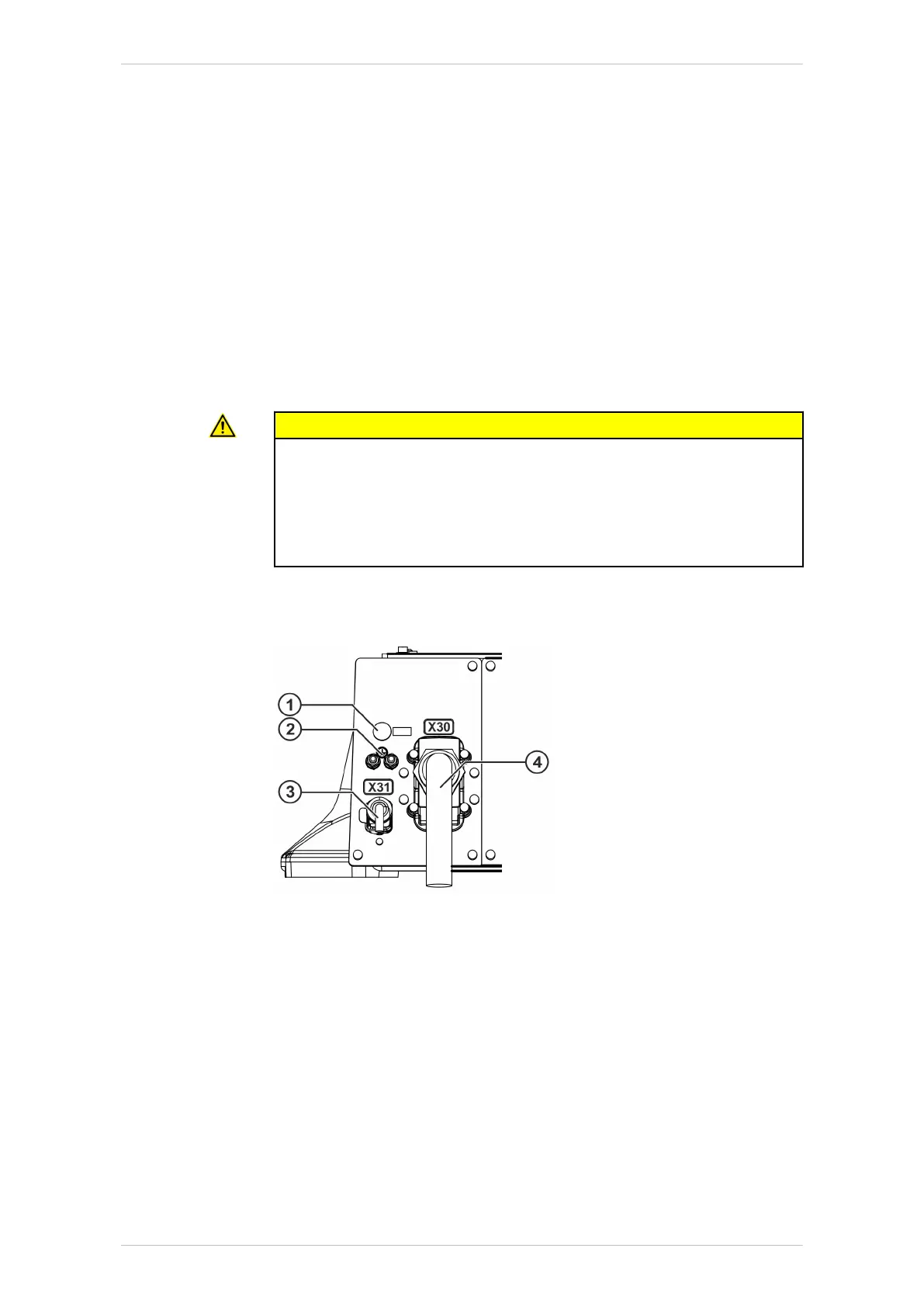
Interface A1
Interface A1 is located at the rear of the base frame.
Fig. 5-4: Interface A1
1 Connection for sealing air (for Foundry only)
2 Ground conductor (2x)
3 Data cable X31
4 Motor cable X30
Interface for energy supply system
The robot can be equipped with an energy supply system between axis 1
and axis 3 and a second energy supply system between axis 3 and ax-
is 6. The A1 interface required for this is located on the rear of the base
frame, the A3 interface is located on the side of the arm and the interface
for axis 6 is located on the robot tool. Depending on the application, the
interfaces differ in design and scope. They can be equipped, for example,
with connections for cables and hoses. Detailed information on the con-
KR IONTEC
164/344 | www.kuka.com MA KR IONTEC V4 | Issued: 11.05.2021
Planning

 Loading...

