2MN/2N1-1
2-2-1
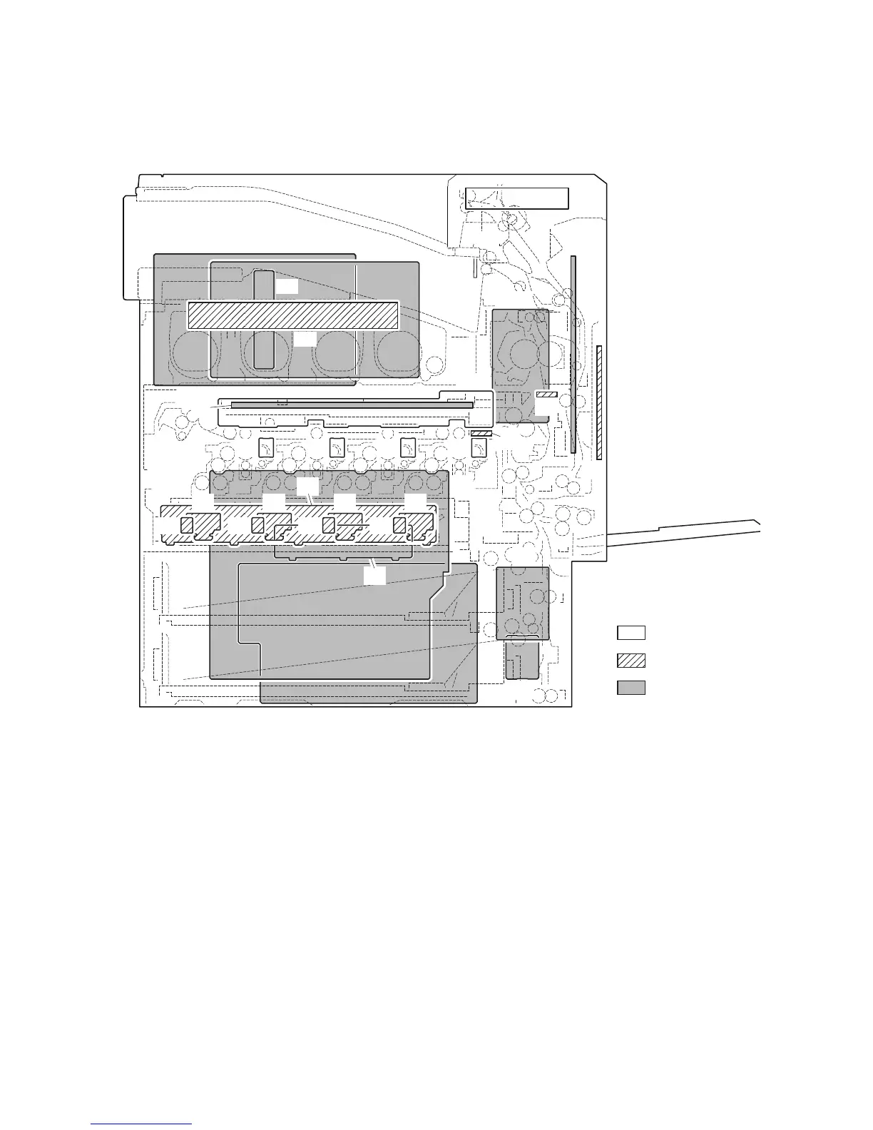
2-2 Electrical Parts Layout
2-2-1 Electrical parts layout
(1) PWBs
Figure 2-2-1 PWBs
1. Main PWB (MPWB) .............................. Controls the software such as the print data processing and
provides the interface with computers.
2. Engine PWB (EPWB)............................ Controls printer hardware such as high voltage/bias output con-
trol, paper conveying system control, and fuser temperature con-
trol, etc.
3. Power source PWB (PSPWB) .............. After full-wave rectification of AC power source input, switching
for converting to 24 V DC and 12 V DC for output.
4. High voltage PWB 1 (HVPWB1) ........... Generates main charging and developer bias.
5. High voltage PWB 2 (HVPWB2) ........... Generates transfer bias and separation bias.
6. Operation PWB (OPWB)....................... Controls keys and LCD indication.
7. Front PWB (FRPWB) ............................ Consists of wiring relay circuit between engine PWB and drum
units, developer units, eject unit.
8. Feed PWB 1 (FPWB1).......................... Consists of wiring relay circuit between engine PWB and fuser
drive unit, relay PWB.
1
2
8
7
21
25
9
30
4
3
12
11
16
20
15
19
14
18
13
17
222324
5
27
10
29
28
6
26
Machine inside
Machine front
Machine rear
 Loading...