Gocator Line Profile Sensors: User Manual
Gocator Web Interface • 221
Parameter Description
Max Width Maximum width of a groove to be considered valid. If set to 0, the maximum is set to the width
of the measurement area.
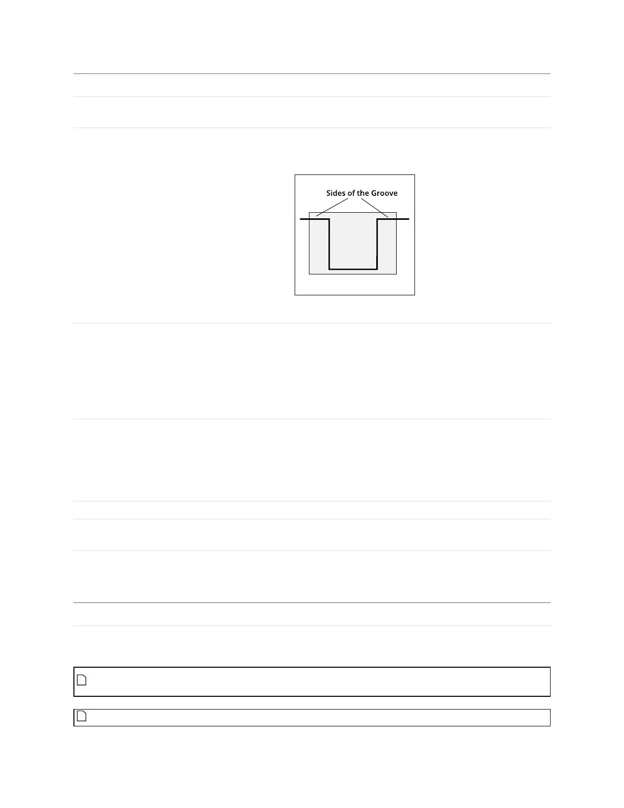
Region The measurement region defines the region in which to search for the groove. For a stable
measurement, the measurement region should be made large enough to cover some laser data
on the left and right sides of the groove.
For more information on regions, see Regions on page 184.
Location
(Groove X and Groove Z
measurements only)
Specifies the location type to return
Bottom - Groove bottom. For a U-shape and open-shape groove, the X position is at the centroid
of the groove. For a V-shape groove, the X position is at the intersection of lines fitted to the left
and right sides of the groove. See algorithm section below for more details.
Left - Groove's left corner.
Right - Groove's right corner.
Select Type Specifies how a groove is selected when there are multiple grooves within the measurement
area.
Maximum Depth - Groove with maximum depth.
Index from The Left - 0-based groove index, counting from left to right
Index from the Right - 0-based groove index, counting from right to left.
Index 0-based groove index.
Filters The filters that are applied to measurement values before they are output. For more
information, see Filters on page 192.
Decision The Max and Min settings define the range that determines whether the measurement tool
sends a pass or fail decision to the output. For more information, see Decisions on page 191.
Anchor Description
X or Z Lets you choose the X or Z measurement of another tool to
use as a positional anchor for this tool.
Anchoring
A measurement must be enabled in the other tool for it to be available as an anchor. The anchor
measurement should also be properly configured before using it as an anchor.
For more information on anchoring, see Measurement Anchoring on page 194.