4-34
Issue 9 October 1998
363-206-204
Powering, Verification, and Circuit Pack Installation
1. Switch sections 7 and 8 are not used prior to Release 6.1 (linear) and Release 7.0 (rings)
and must be set to the
ON
position. If they are set to the
OFF
position, the
FAULT LED
on the
SYSCTL
will light and an alarm will be generated.
2. Only site addresses 1-8 are supported prior to Release 6.1 (linear) and Release 7.0
(rings). For releases prior to these, if more than 8 sites are allowed, you should use
unique combinations of the Site ID(SYSTCTL) and NE(OHCTL) settings to prevent dupli-
cate site/ne settings in the same subnetwork.
3. Site addresses 1-10 are supported for Release 6.1 (linear) and Release 7.0 (rings), or
later. Switch sections 7 and 8 are used in conjunction with sections 1, 2, and 3 to support
the new site addresses.
4. Site addresses 11-16 are will be supported in Release 7.1 (rings) and then only when
interworking with OC-12. Switch sections 7 and 8 are used in conjunction with sections 1,
2, and 3 to support the new site addresses.
5. Site addresses 11-32 are will be supported in future releases. Switch sections 7 and 8
are used in conjunction with sections 1, 2, and 3 to support the new site addresses.
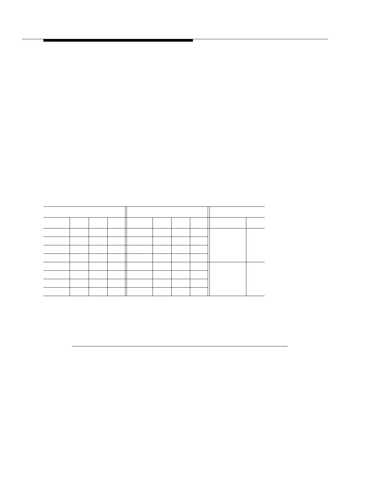
SYSCTL Switch 3 Notes
:
1. Switch section 8 must be set to OFF.
2. An invalid data rate setting will revert to 1200 baud, generate an alarm, light the SYSCTL
FAULT LED, and set TBOS point 14.
Figure 4 -7. BBG5 (SYSCTL) Option Switches (Sheet 4 of 5)
Switch 3 Settings
Front Access Data Rate Rear Access Data Rate Power Minor
Value Sec 1 Sec 2 Sec 3 Value Sec 4 Sec 5 Sec 6 Value Sec 7
300 OFF OFF OFF 300 OFF OFF OFF Office Minor OFF
1200 OFF OFF ON 1200 OFF OFF ON
2400 OFF ON OFF 2400 OFF ON OFF
4800 OFF ON ON 4800 OFF ON ON
9600 ON OFF OFF 9600 ON OFF OFF Office Major ON
19200 ON OFF ON 19200 ON OFF ON
(Invalid) ON ON OFF (Invalid) ON ON OFF
(Invalid) ON ON ON (Invalid) ON ON ON