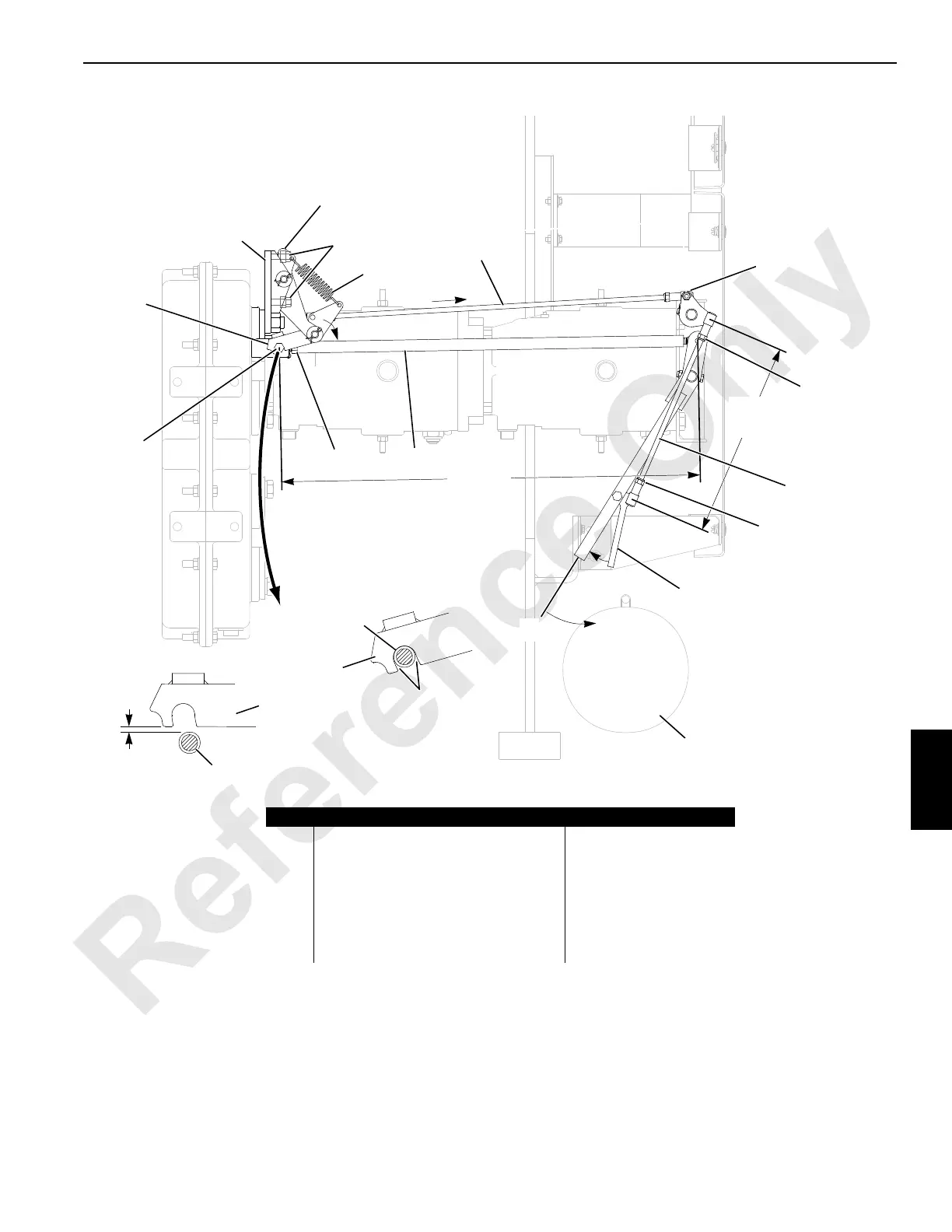
FIGURE 7-13
Disengage
Engage
3 mm
(1/8 in)
View B
699 mm
(27-1/2 in)
View A
No Interference
Either Side
327 mm
(12-7/8 in)
9
1
2
3
4
7
5
6
8
11
10
12
11
2
1
1
14
13
2
Item Description Item Description
1 Latch Assembly 8 Hex Nut
2Hook 9 Shift Rod
3 Base Plate 10 Ball Joint (qty 2)
4 Rocker Arm 11 Elastic Stop Nut (qty 2)
5 Set Screw with Lock Nut (qty 2) 12 Pull Rod
6 Spring 13 Squeeze Trigger
7 Control Rod 14 Left Rear Jacking Cylinder
 Loading...


