Manitowoc Published 07-19-16, Control # 249-01 1-39
2250 SERVICE/MAINTENANCE MANUAL INTRODUCTION
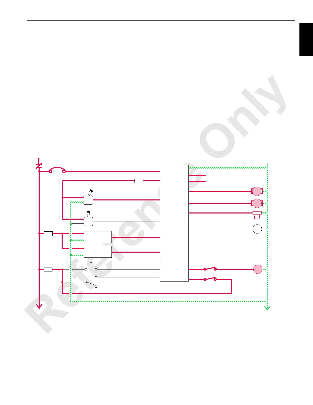
The travel pump’s EDC tilts the pump’s swashplate in the
forward direction. Hydraulic fluid flow is from the pump port
of the selected travel pump through a quick disconnect and
swivel to the travel motor. The PC input voltage to a selected
travel pump’s EDC is relative to the selected control handle’s
movement.
When a travel control handle is moved in a reverse direction,
an input voltage of 5 V or less is sent to the PC. The PC
sends a variable plus 0 to 2.8 V output that is applied to the
selected travel pump’s EDC. The PC sends a 12 V output to
enable the travel brake solenoid valve HS-1. The travel
brake solenoid valve is enabled to release both the left and
right crawler brakes, before the selected travel pump
strokes.
The travel pump’s EDC tilts the motor’s swashplate in the
reverse direction. Hydraulic fluid flow is from the pump port
of the selected travel pump through the swivel to the motor
port. The PC sends an input voltage to the selected travel
pump’s EDC that is relative to the selected control handle’s
movement.
Travel motors are variable-displacement and shift internally
with an adjustable spring in each motor’s P/C valve, preset at
270 bar (3,915 psi). Travel motors are in the minimum
displacement (low-torque, high-speed) position when
starting. When the crawler begins to move, a high system
pressure shifts the PCOR spool, placing the travel motor in
the maximum displacement (high-torque, low-speed)
position for breakaway torque.
As the travel control handle nears the neutral position, the
PC compensates for hydraulic system leakage or changing
engine speed. The PC sends a 0 V output to the pump’s
EDC to move the swashplate to the center position. After the
travel control handle command is in the OFF position for a
preset time, a 0 V output is sent to disable the travel brake
solenoid valve HS-1. The travel brake solenoid valve shifts to
block pilot pressure to the brakes and opens a line to the
tank, and the brakes apply.
RF-15
50 Amp
8P1
87FA 10 V Regulated Supply
WA-07
WA-01
Control Handle
K1
8
Reverse
5A
F16
3A
Forward
F12
5A
8T
F10
5A
8D
Crane Display
WD-19
WD-20
WC-23
Left Travel Pump
EDC
B
A
0
Ground
Left Travel
Pressure
Sender
Right Travel
Pressure
Sender
WA-28
WA-27
Swing/Travel Alarm
WD-35
High-Speed Travel Switch
WA-06
Control Handle
Reverse
Forward
Left Travel
Right Travel
WC-15
Right Travel Pump
EDC
B
A
WB-01
Travel Detent
WB-15
HS
35
HS
1
Two-Speed Travel
WC-32
WB-19
WC-10
Travel Brake
Programmable
Controller
FIGURE 1-22
 Loading...


