Manitowoc Published 07-19-16, Control # 249-01 1-51
2250 SERVICE/MAINTENANCE MANUAL INTRODUCTION
Begin applying the load drum working brake pedal as the
selected control handle is moved to the OFF position to hold
the load when the PC releases the clutch from the drum
shaft.
As the working brake pedal is released, the load starts to free
fall. Lowering speed must be controlled with the working
brake pedal.
WARNING
Falling Load Hazard!
Avoid possible injury. When the working brake pedal is
released, the load on the drum free falls. The working
brake pedal controls lowering speed. A hoisted load in
Free Fall mode will fall unless stopped by the brake pedal.
WARNING
Falling Load Hazard!
Avoid possible injury. The load will fall uncontrolled if
working brake pedal is not applied before moving control
handle to the OFF position.
RF-23
50 Amp
8P1
10 V Regulated Supply
WA-03
WA-01
Left (drum 1) Control Handle
K1
8
Raise
5A
F16
3A
Lower
F11
5A
8E
Crane Display
WD-19
WD-20
WC-05
Pump Control 1
P/C
B
A
0
Ground
Main Charge
Pressure
Sender
WA-25
WA-22
WE-04
WE-03
8E
0
AS
19
87FA
WC-26
Left Rotation Indicator
Drum 2 Pawl In
WE-36
WA-04
Right (drum 2/3) Control Handle
Raise
Lower
Main Hoist
Pressure
Sender
Right Rear
Speed
Sender
F
A
B
D
(drum 2)
WC-06
Pump Control 2
P/C
B
A
WD-25
Main Hoist Motor Control
PCP
B
A
AS
20
Drum 2 Pawl Out
WE-37
AS
10
Drum 2 Clutch
WC-17
AS
9
WB-27
WC-08
Drum 2 Brake
Drum 2 Free Fall Light
WD-36
F12
5A
8E
Right Rear Drum
WB-23
Free Fall Safety
WB-20
Low Air Pressure
WD-34
Opt. Main Motor Control
PCP
B
A
AS
8
Drum 1 Clutch
WC-16
AS
12
Drum 3 Clutch
WC-18
Amber
WC-20
Opt. Main Pump Control
B
A
WC-29
C
D
P/C
Minimum Bail Limit (drum 2)
WB-08
Maximum Bail Limit (drum 2)
WB-07
F10
5A
8D
WB-22
Left Rear Drum
Controller
Programmable
Right Handle Drum 2 Light
WC-11
Green
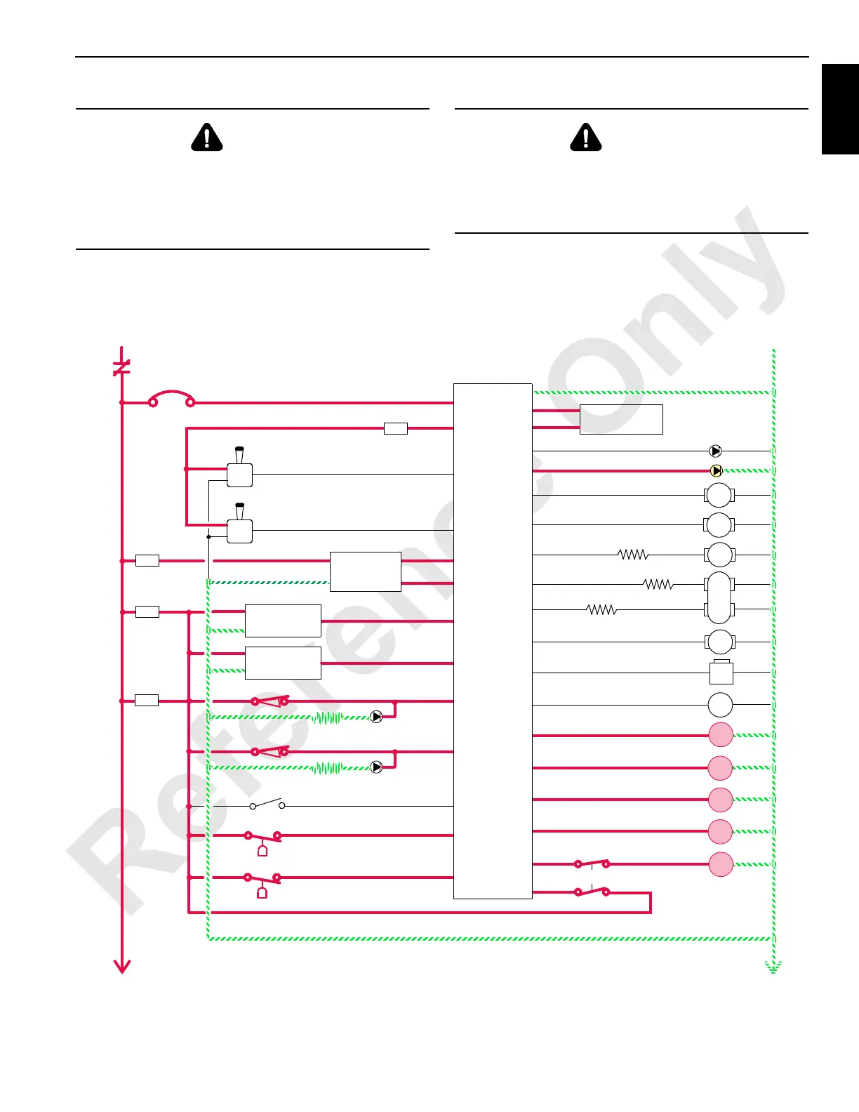
FIGURE 1-30
 Loading...


